

Method for connecting gigabit interface converters with serial identification capability into an active two-wire serial bus
a serial bus and converter technology, applied in the direction of electrical instruments, electric digital data processing, electrical apparatus, etc., can solve the problem of high undesirable bus lockup
- Summary
- Abstract
- Description
- Claims
- Application Information
AI Technical Summary
Benefits of technology
Problems solved by technology
Method used
Image

Examples
first embodiment
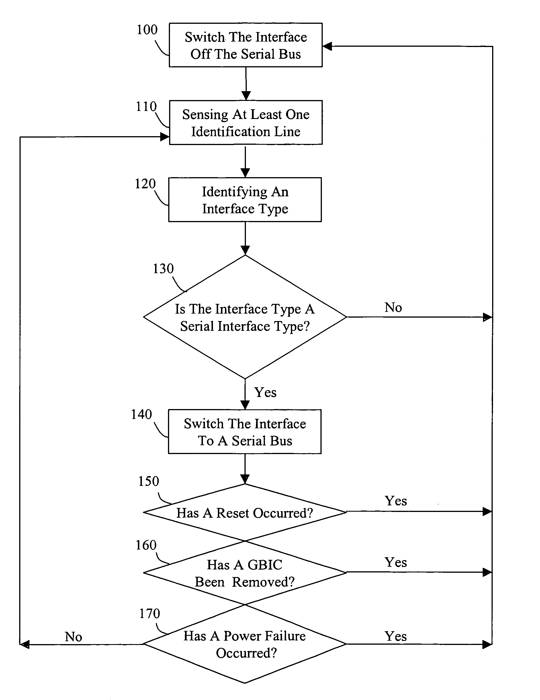
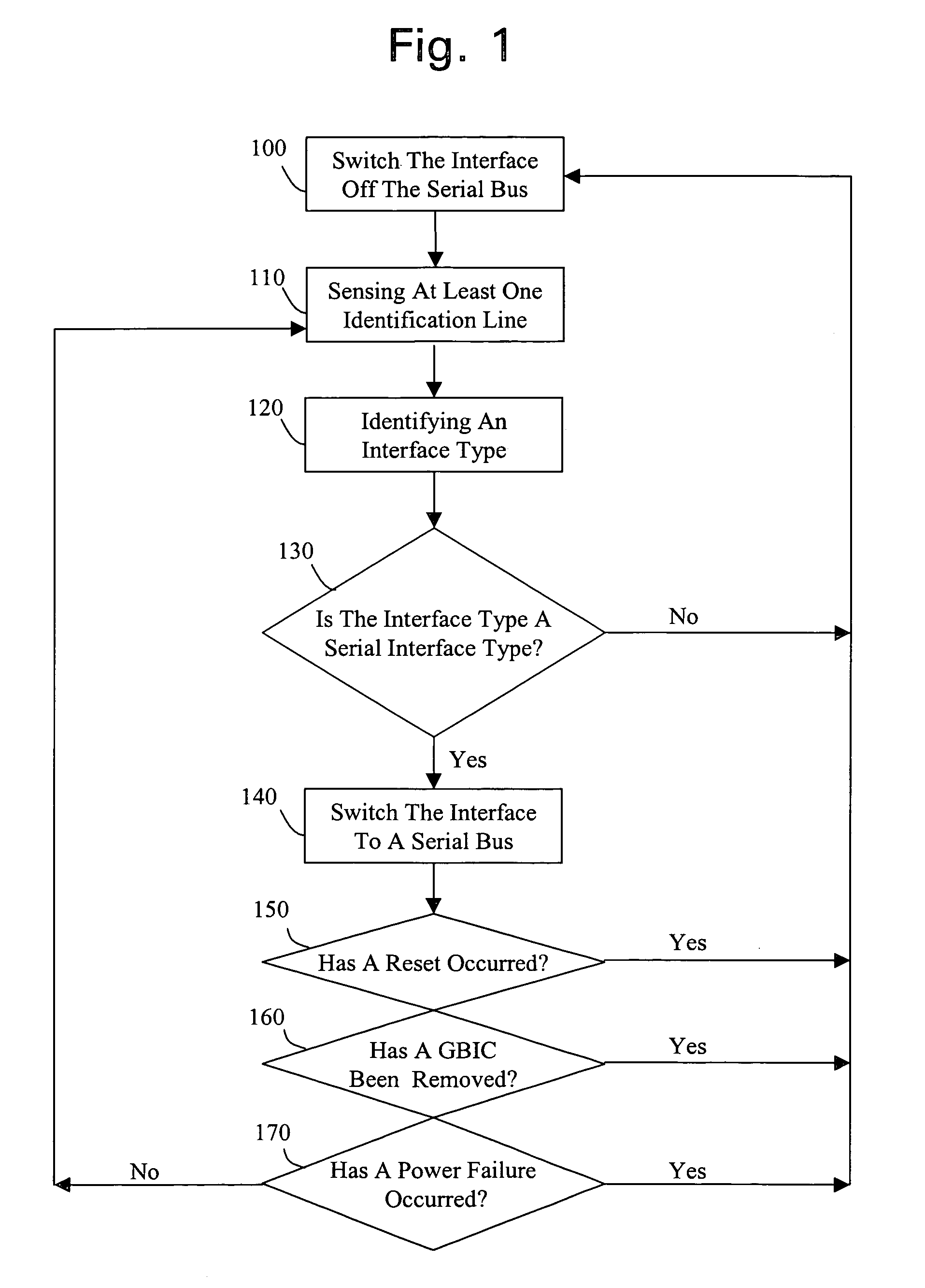
[0024]a method for connecting an interface to a serial bus is shown by the block diagram of FIG. 1. By way of example, FIG. 1 will be described with reference to a GBIC implementation. Other interface configurations having a shared serial bus may also be implemented as would be readily apparent to one skilled in the art.
[0025]An interface according to this first embodiment, senses at least one identification line in step 110. For a GBIC implementation, the interface senses three TTL-compatible signal lines MOD—DEF[2..0] in step 110. In step 120, the interface identifies an interface type from the at least one identification line sensed in step 110. A Module Definition 4 serial definition protocol, for example, may be identified from the eight possible GBIC module definitions.
[0026]In step 130, the interface determines whether the interface type identified in step 120 is a serial interface type. The interface then uses a criteria to determine whether or not to switch the interface on...
second embodiment
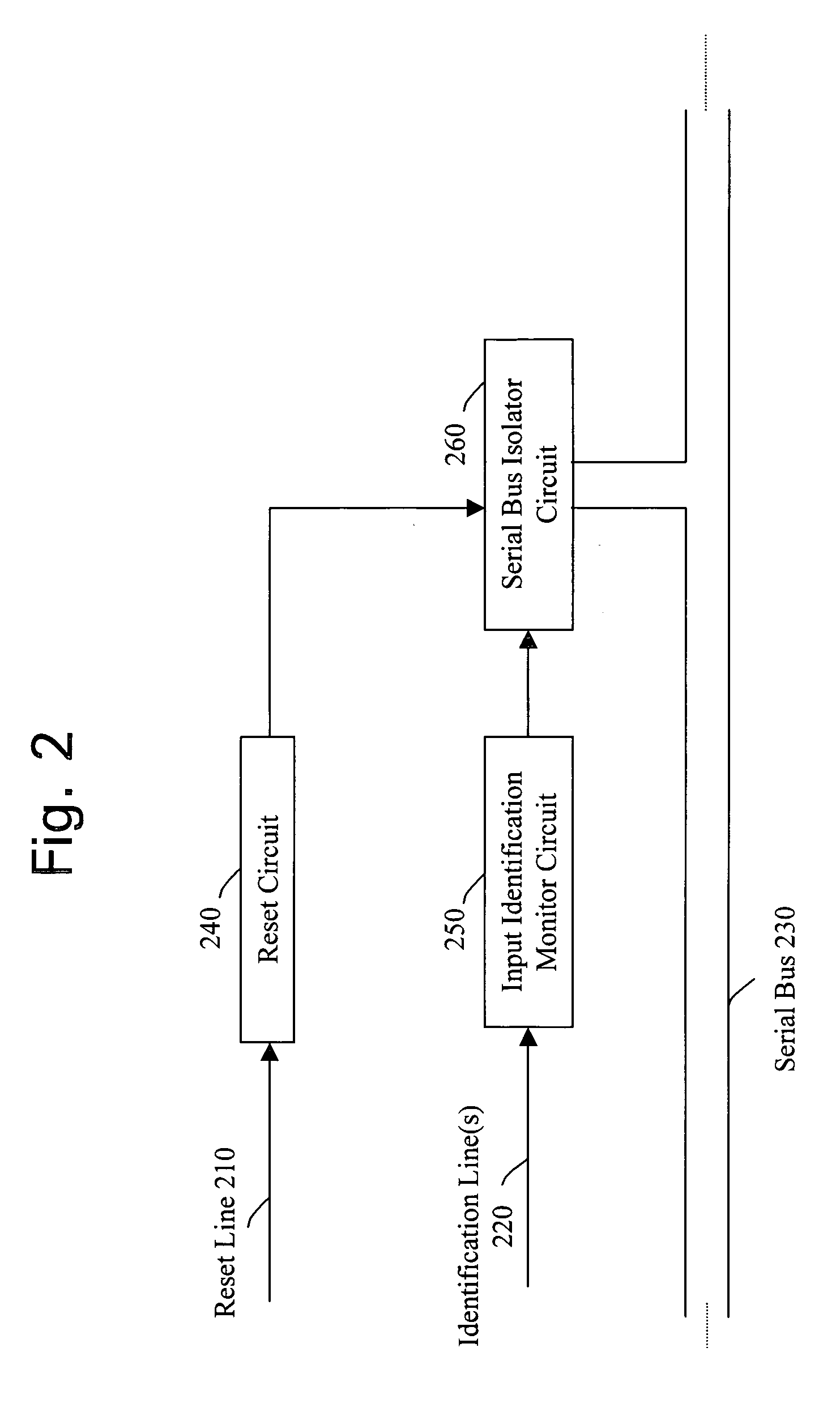
[0033]An interface according to this second embodiment monitors at least one identification line 220 via an input identification monitor circuit 250. The interface utilizes a serial bus isolator circuit 260 to permit the interface to transmit via the serial bus 230 when a serial interface configuration is identified via the input identification monitor circuit 250.
[0034]Optionally the serial bus isolator circuit 260 isolates the serial bus interface from the serial bus 230 during any one of a number of conditions. For example, the serial bus isolator circuit 260 may isolate the serial bus interface from the serial bus 230 during power up and / or power failure. Further, the serial bus isolator circuit 260 may isolate the serial bus interface from the serial bus when the input identification monitor circuit 250 detects a change in interface type and / or when an interface type is removed (e.g. an operator disconnecting an interface cable from the interface).
[0035]Optional reset circuit 2...
third embodiment
[0038]According to this third embodiment, MOD—DEF—SENSE1 and MOD—DEF—SENSE2 may be connected to an external device such as a system computer or monitoring lights, to provide additional command and / or control of the configurable serial bus interface. External computer monitoring may be utilized, for example, to perform system wide command and control including enabling (e.g. GBIC—TWS—EN) and / or resetting (e.g. RS—RESET) the configurable serial bus interface 300. As shown, some or all of the identification lines 310 may be ANDed together by AND gate 367 (e.g. MOD—DEF[1] and MOD—DEF[2] as shown in FIG. 3) depending on the particular configuration.
[0039]The function of this third embodiment will now be described in reference to FIG. 3. During power up, the GBIC—TWS—EN is set to a TTL low, thereby providing a TTL low on the output line 321 of the input monitoring circuit 320. The TTL low output is provided to gates 366 and 376 of transistors 365 and 370 in the serial bus isolator circuit...
PUM
 Abstract
Description
Claims
Application Information