Automatic positioning of display depending upon the viewer's location

a technology of automatic positioning and viewer's position, applied in the field of displays, can solve the problem that the system only provides an approximate positioning, and achieve the effect of less discrimination and adjustmen

Inactive Publication Date: 2005-08-16
KONINKLIJKE PHILIPS ELECTRONICS NV
View PDF14 Cites 166 Cited by
  • Summary
  • Abstract
  • Description
  • Claims
  • Application Information

AI Technical Summary

Problems solved by technology

One obvious difficulty with the prior art systems is that they either require a user use a remote (as in the Yu patent) to adjust the position of the display.
In addition, the Yu system only provides an approximate positioning based on a limited array of photo detectors.

Method used


Image

  • Automatic positioning of display depending upon the viewer's location
  • Automatic positioning of display depending upon the viewer's location
  • Automatic positioning of display depending upon the viewer's location

Examples


Embodiment Construction

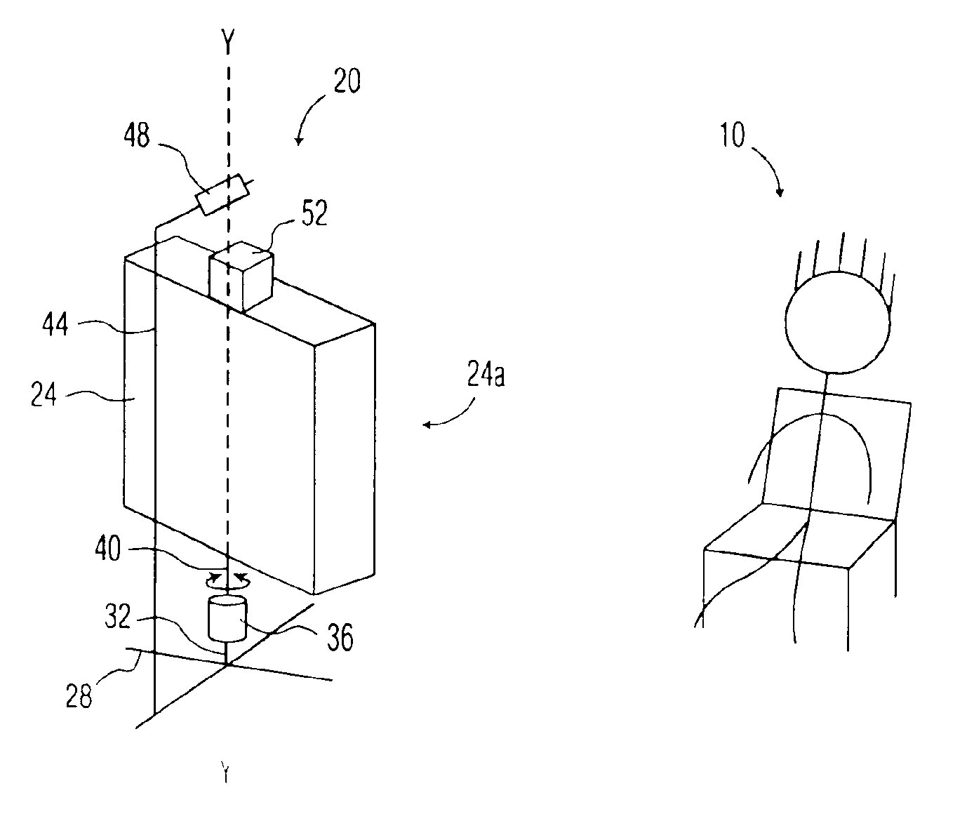
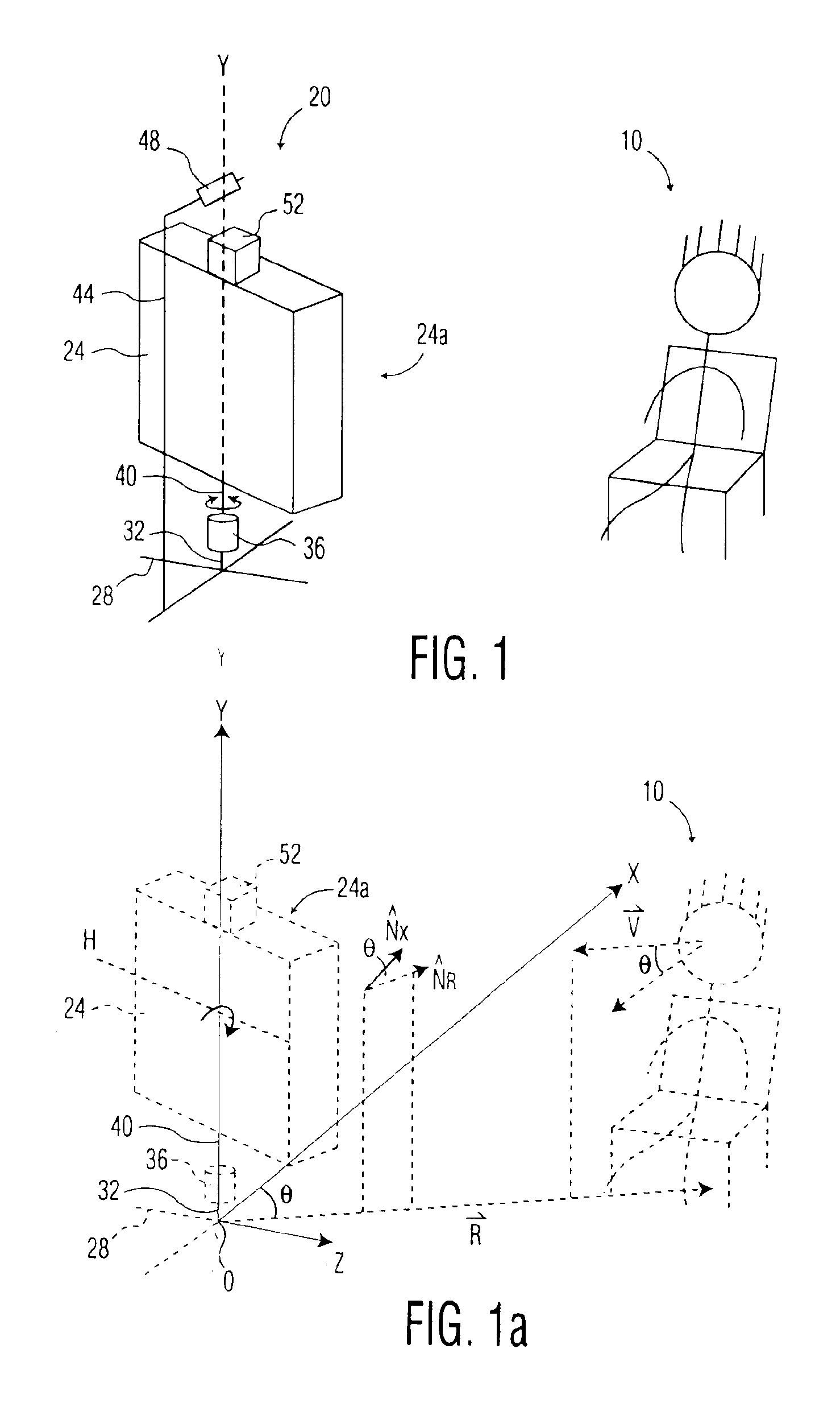
[0015]Referring to FIG. 1, a user 10 is shown positioned in a viewing region of a system 20 comprising an embodiment of the invention. The system 20 is comprised of a display 24 having a display screen 24a that may be viewed by the user 10 (thus the user is in the “viewing region” of the system 20, as noted above). The display 24 is supported by a base 28, which includes lower and upper vertical supports 32, 40 having a stepper motor 36 interposed therebetween. The base 28, lower vertical support 32 and stepper motor 36 are in a fixed relationship relative to each other. Upper vertical support 40 may be rotated along its axis by the drive shaft of stepper motor 36 (as indicated by the arrow shown in FIG. 1 adjacent the upper vertical support 40). Thus, as described further below, the display may be rotated by the stepper motor 36 about the axis Y (defined by vertical support 40) to orient the display screen 24a so that it faces the user 10.

[0016]The system 20 is also comprised of a ...


PUM


Abstract

A system having a video display screen that provides video to a user. The position of the display screen is adjustable based upon the location of the user with respect to the display screen. The system includes at least one image capturing device trainable on a viewing region of the display screen and coupled to a control unit having image recognition software. The image recognition software identifies the user in an image generated by the image capturing device. The software of the control unit also generates at least one measurement of the position of the user based upon the detection of the user in the image.

Description

FIELD OF THE INVENTION[0001]The invention relates to displays, such as computer monitors, televisions and home theater systems. In particular, the invention relates to systems and methods for adjusting the position of the screen of such displays with respect to one or more viewers.BACKGROUND OF THE INVENTION[0002]Particular systems for adjusting the direction that a video display is oriented based on the position of a viewer are known. For example, the Abstract of Japanese Patent Application 04290019 (publication number 06141309) describes a system that utilizes two microphones that each sample the voice of a talking person. The system compares the samples from each microphone to determine which is larger. The system purportedly uses the comparison to orient a display in the direction of the person. Among other disadvantages, the system cannot precisely orient the display in the direction of the user based solely upon which microphone detects a larger speaking volume. In addition, t...

Claims


Application Information

Patent Timeline
Patent Type & Authority Patents(United States)
IPC IPC(8): G06F3/00G10L15/00G10L15/26G09F11/00H04N5/44H04N5/74H04H9/00H04N5/64G06T1/00G06F3/01G06T7/20G09G5/00H04H60/31H04N5/66H04N7/18
CPCG06F3/011G09F11/00H04N5/44H04N5/74H04N5/64H04N21/44218G06F3/00
Inventor GUTTA, SRINIVASKURAPATI, KAUSHALCOLMENAREZ, ANTONIO J.
Owner KONINKLIJKE PHILIPS ELECTRONICS NV
Why Eureka
Try Eureka