Permanent magnet flowmeter with noncircular sensing passage

Inactive Publication Date: 2005-08-23
MEDTRONIC INC
View PDF22 Cites 29 Cited by
  • Summary
  • Abstract
  • Description
  • Claims
  • Application Information

AI Technical Summary

Problems solved by technology

This poses an isolation problem and may be

Method used


Image

  • Permanent magnet flowmeter with noncircular sensing passage
  • Permanent magnet flowmeter with noncircular sensing passage
  • Permanent magnet flowmeter with noncircular sensing passage

Examples


Embodiment Construction

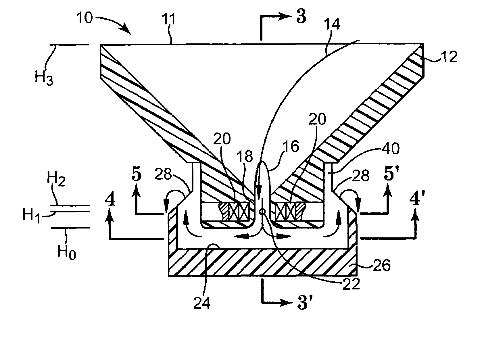
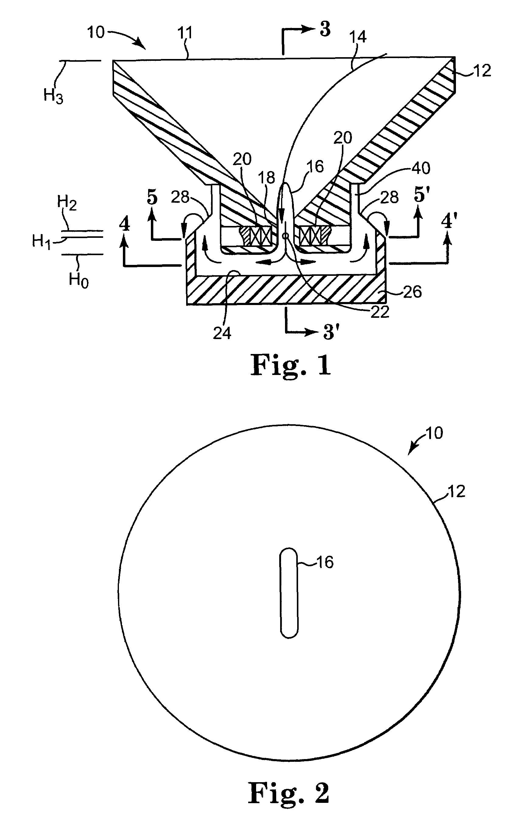
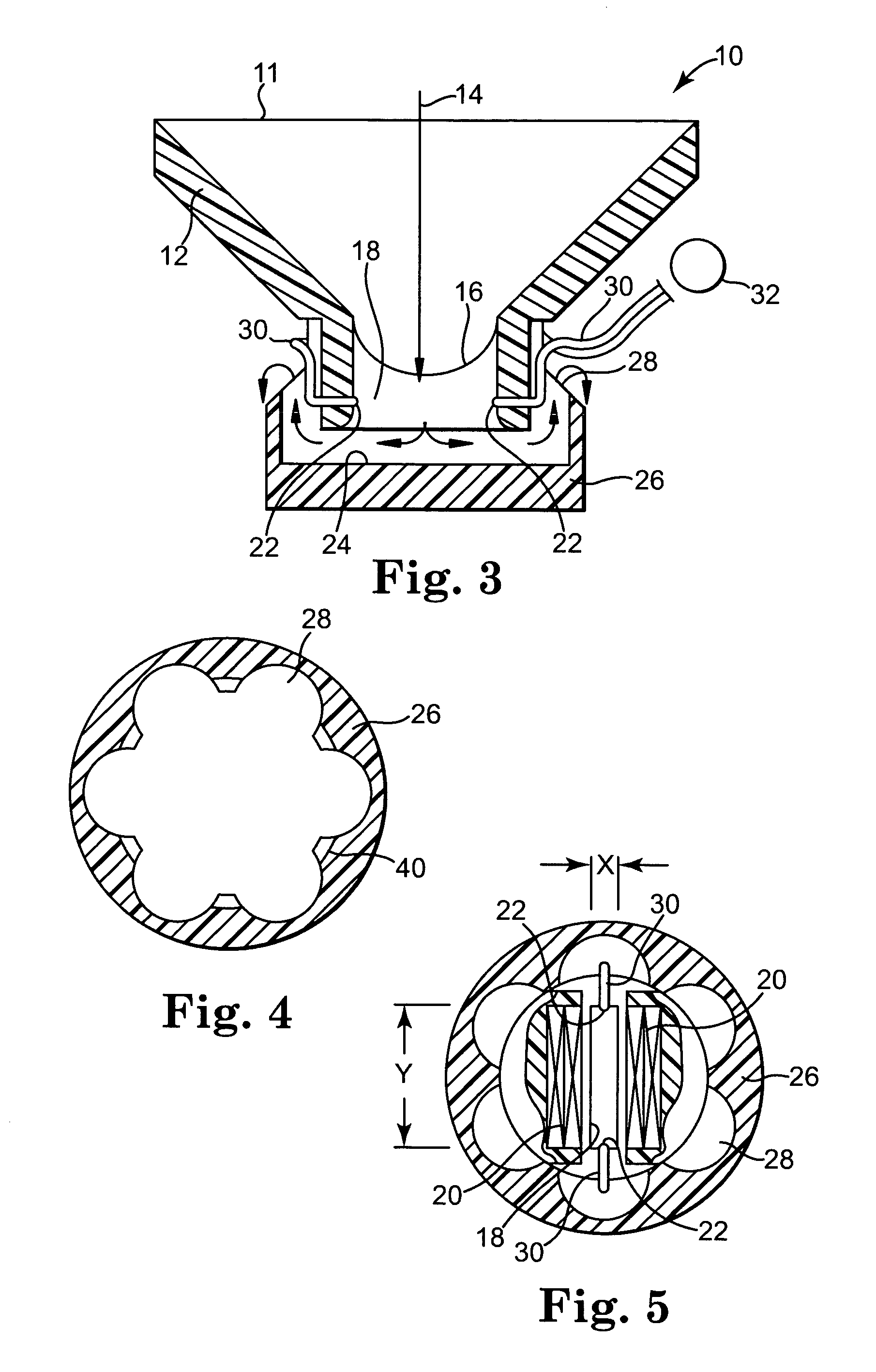
[0019]When used to describe the elevation, location, orientation or motion of elements or liquids in the disclosed devices, words such as “upward”, “downward”, “higher”, “lower”, “above”, “below” and the like refer to the relative position of an element or liquid portion with respect to another element or liquid portion when the disclosed device is being used in its normal orientation for measurement of liquid flow, and are not intended to require that the disclosed devices should have any particular orientation in space during manufacture or storage.

[0020]When used with respect to a liquid flow measurement device, the phrase “gravity-assisted” refers a generally downward liquid flow path from an initial higher elevation upon entry into the device to an eventual lower elevation upon exit from (or settling within) the device.

[0021]The phrase “in fluid communication” refers to an available liquid flow path from a first region or location in a device to a second region or location in t...


PUM


Abstract

A passive flowmeter having an inlet, sensing passage and outlet in fluid communication with one another, the sensing passage having a noncircular cross-section having a minor axis generally aligned with a permanent magnetic field and a major axis generally aligned with at least a pair of generally opposed electrodes for detecting a flow-dependent voltage induced by the passage of conductive liquid through the magnetic field. By using both permanent magnets and a noncircular cross-section sensing passage together in the same device, much greater latitude in magnet selection may be obtained. This may facilitate for example the use of lower cost permanent magnets and the construction of a lower cost device for disposable flowmeter applications.

Description

TECHNICAL FIELD[0001]This invention relates to liquid flow rate measurement.BACKGROUND[0002]Flowmeters are used to measure liquid flow rates or volumes. A variety of devices have been employed, including weight cells, rotameters, spinning disk or spinning rotor sensors, capacitive sensors, pressure sensors and Faraday effect sensors. References describing such devices include U.S. Pat. Nos. 4,008,609, 4,099,412, 4,118,981, 4,145,924, 4,434,667, 4,683,748, 4,732,160, 4,881,413, 4,899,592, 5,046,510, 5,062,304, 5,078,012, 5,176,148, 5,207,105, 5,325,728, 5,327,787, 5,495,854, 5,708,212, 6,237,424 B1 and 6,463,807 B1.SUMMARY OF THE INVENTION[0003]Some flowmeters employ electrically energized or moving parts (e.g., electromagnets, motors or weight cells) and thus may require electrical excitation using an external or onboard power supply. This poses an isolation problem and may be undesirable in, e.g., medical applications.[0004]The invention provides, in one aspect, a passive flowmeter...

Claims


Application Information

Patent Timeline
IPC IPC(8): G01F1/58G01F1/56G01F15/18
CPCG01F1/58G01F1/588G01F15/185
Inventor AUNDAL, KNUD TORP
Owner MEDTRONIC INC
Why Eureka
Try Eureka