Maneuvering of submerged waterjet propelled sea craft

Active Publication Date: 2005-08-23
NAVY DEPT OF
View PDF5 Cites 21 Cited by
  • Summary
  • Abstract
  • Description
  • Claims
  • Application Information

AI Technical Summary

Benefits of technology

[0005]In accordance with the present invention, all maneuvering operations of an underwater jet propulsion system are performed by selectively controlled diversion of pressurized water through main water flow channels into secondary flow channels past flow smoothing vanes for controlled outflow discharge as the propulsion jets emerging from openings in the hull in one direction perpendicular to the hull centerline for steering purposes and in another direction at an acute negative thrust angle for backing and stopping purposes. Such directional outflow discharge jets are conducted to the hull openings from the secondary channels through subchannel branches under selective control of either closure gates at the hull openings or hinged juncture flow diverting flappers between the subchannels branches.

Problems solved by technology

According to U.S. Pat. No. 6,171,159 issued January 2001 to Shen et al., surface ships propelled by underwater jet discharge are provided with steering and backing types of maneuvering systems, not suitable however for a submerged sea craft.

Method used


Image

  • Maneuvering of submerged waterjet propelled sea craft
  • Maneuvering of submerged waterjet propelled sea craft
  • Maneuvering of submerged waterjet propelled sea craft

Examples


Embodiment Construction

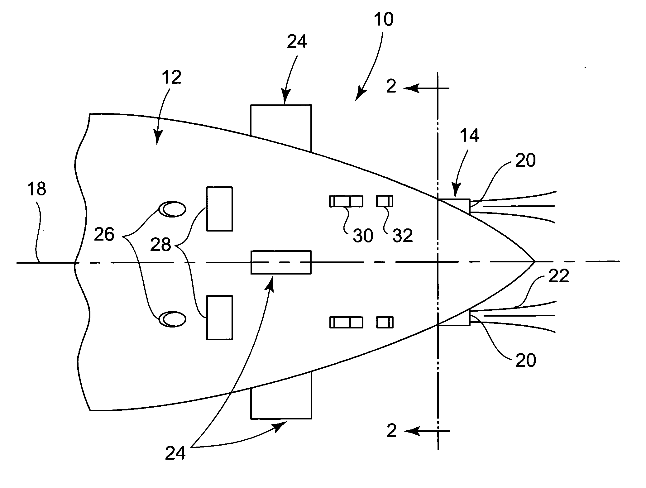
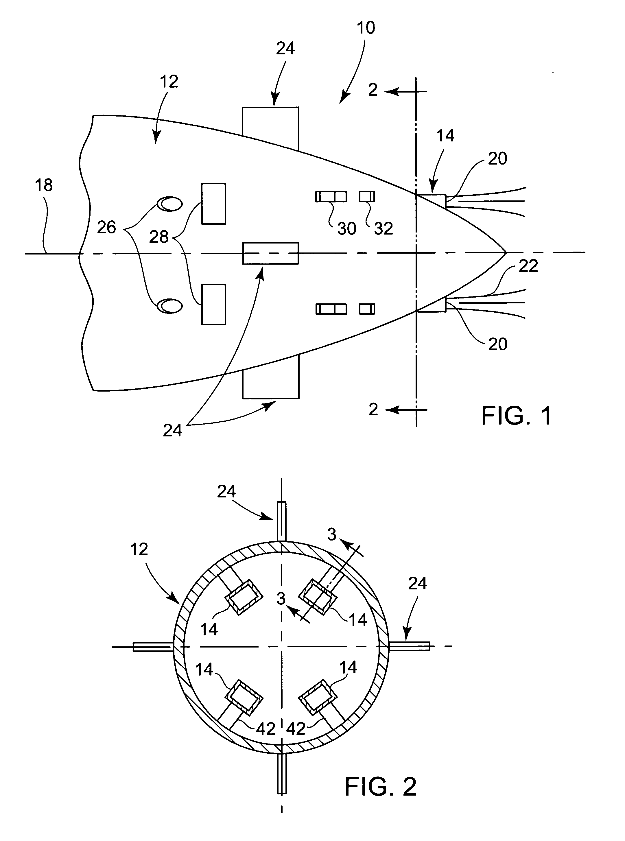
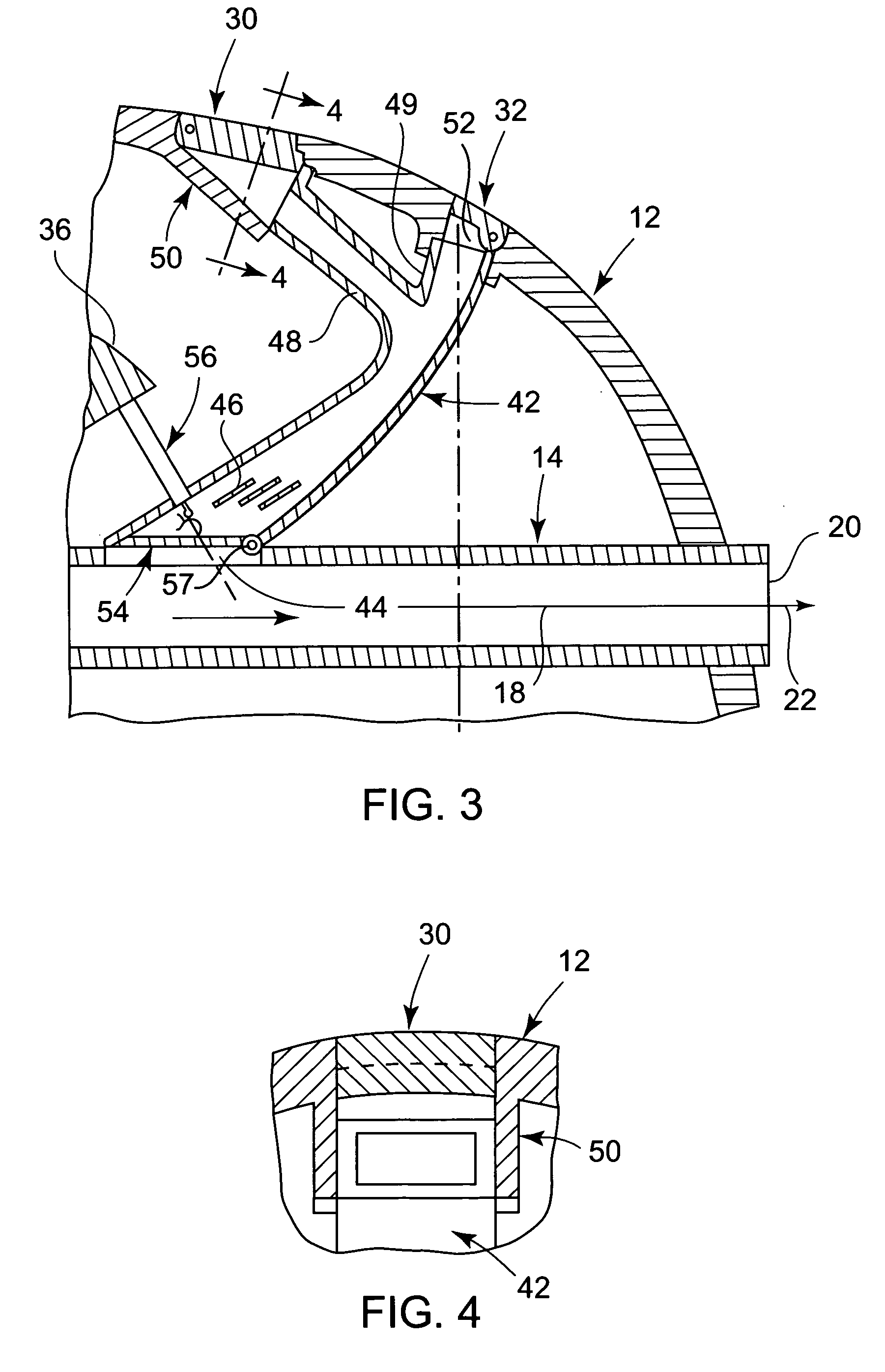
[0017]Referring now to the drawing in detail, FIGS. 1–4 illustrate the stern portion of an underwater submerged ship or sea craft 10 having a generally conical-shaped hull 12 enclosing a ballast tank therein. The craft 10 is propelled in a forward direction by water jet propulsion on the stern portion of the hull 12 as generally known in the art, involving four (4) main tubular water outflow channels 14 extending from propulsors as disclosed for example in U.S. Pat. No. 6,171,159 to Shen et al. The channels 14 extend through the stern portion of the hull 12 in parallel spaced relation to the hull centerline 18. Stern outflow nozzles 20 at the ends of the channels 14 project from the hull 12 for emergence of propelling water jets 22 as shown in FIG. 1. Conventional rudders 24 are mounted on and project from the hull 12 between the main channels 14, spaced forwardly of the nozzles 20 along the hull centerline 18.

[0018]The foregoing referred to jet propulsion system for the sea craft 1...


PUM


Abstract

The stern hull portion of a sea craft through which main exit flow channels extend to projecting jet propulsion nozzles, is provided with facilities for controlled maneuvering of the sea craft, including steering, stopping, negative thrust backing and docking without substantial hydrodynamic loading and with facilitated installation. Such maneuvering control facilities include a secondary flow channel extending from each of the main exit flow channels having two angularly related subchannel branches for pressurized water outflow through gated openings in the hull from which propulsion jets emerge under maneuvering control. Either control of a subchannel diverting flapper, or by use of selective closure gates and a flow diverting flap within the main exit flow channel, maneuvering may be effected in response to inflow through inlet openings in the hull of water that is pressurized before supply to the main exit flow channels.

Description

STATEMENT OF GOVERNMENT INTEREST[0001]The invention described herein may be manufactured and used by or for the Government of the United States of America for governmental purposes without the payment of any royalties thereon or therefore.[0002]The present invention relates to the maneuvering of sea craft having water jet propulsors.BACKGROUND OF THE INVENTION[0003]Water jet propulsion of marine vessel hulls as compared to screw propeller systems are more flexible in usage, involve less mechanical equipment for hull installation and provide for improved maneuverability of the ship being propelled. Conventional maneuvering systems for water jet propulsors include water intake motors and pumps for water inflow through hull inlets and accelerated nozzle outflow of the propulsion jets above the hull waterline. Heretofore commercial ships with such water jet propulsors utilized jet deflecting buckets, sleeves and vanes for effective steering and backing purposes, involving above water je...

Claims


Application Information

Patent Timeline
Patent Type & Authority Patents(United States)
IPC IPC(8): B63H25/46B63G8/00B63G8/20B63H25/00B63G8/16
CPCB63G8/16B63H25/46
Inventor SHEN, YOUNG T.DAI, CHARLES M.COX, BRUCE D.
Owner NAVY DEPT OF
Why Eureka
Try Eureka