Field configurable shut-off valve

a shut-off valve and field technology, applied in the field of valves, can solve the problems of affecting the quality of the valve, affecting the service life of the valve, and affecting the service life of the valve, and achieving the effect of reducing the processing and delivery time, and reducing the cost of the valv

Inactive Publication Date: 2005-08-23
DAHL BROS CANADA
View PDF14 Cites 13 Cited by
  • Summary
  • Abstract
  • Description
  • Claims
  • Application Information

AI Technical Summary

Benefits of technology

[0028]In a fourth aspect of the invention, a self-contained valve body for field assembly of a shut-off valve with field selectable connection fittings is provided. The valve body has a valve housing with a plurality of ports, each of the ports having a longitudinal axis and a first connector end for receiving a connection fitting. The valve body further has a valve closure member mounted within said the housing, a valve handle for moving the valve closure member between open and closed positions, and internal flow passageways for permitting the flow of fluid among the plurality of ports through the valve closure member. The valve body also has a ball valve sealing structure to provide leak-proof operation of the valve closure member when in, and moving between, the open and closed positions. The assembly and operation of the ball valve sealing structure is independent of the connection fittings received in the ports.

Problems solved by technology

Stocking a comprehensive inventory of valves is therefore a difficult and costly task.
For plumbers or pipefitters, it is generally cost prohibitive to carry a large inventory.
Plumbers may have sources from which specific valves can be ordered, but receiving the valve is of course delayed by processing and delivery time.
Alternatively, plumbers may have access to wholesale suppliers but such suppliers are not usually open in evenings or on weekends.
As a result this may cause considerable delay and inconvenience.
However, these retailers are also reluctant to incur the high cost of inventory associated with stocking ready-to-use valves in numerous variety, or to give up the large amount of shelf space which such a variety of valves would require.
The manufacturer therefore achieves inventory cost reductions and convenience by following the teaching of the patent, but such benefits are not experienced by plumbers or do-it-yourself homeowners, or retailers on which they rely.
However, since a user in the field cannot be expected to have specialized equipment for tightening of the connection fittings, offering the kit of parts of the '307 patent to such a user may be of no benefit.
Furthermore, factory assembly of the parts of the '307 patent permits leak testing of the valve open / close operation at the factory.

Method used


Image

  • Field configurable shut-off valve
  • Field configurable shut-off valve
  • Field configurable shut-off valve

Examples


Embodiment Construction

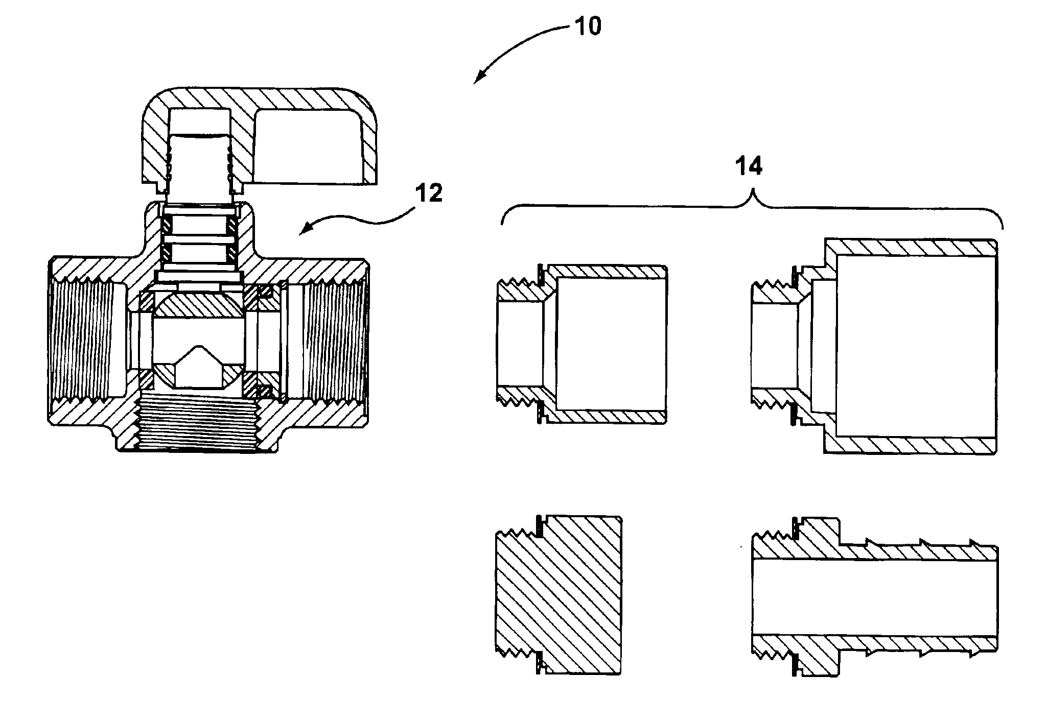
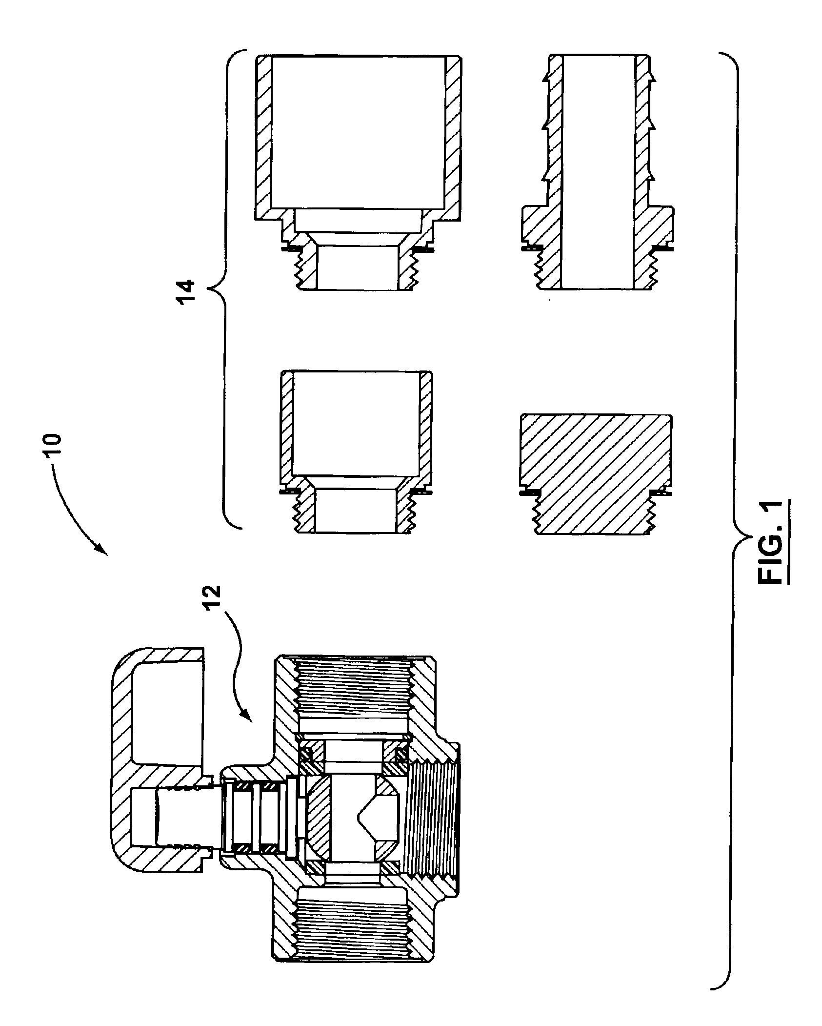
[0063]A kit of parts for assembly of a shut-off valve is shown generally at 10 in FIG. 1. The kit of parts 10 comprises a valve body 12 and a plurality of connection fittings 14. All connection fittings 14 have certain portions with a common configuration and certain portions with differing configurations.

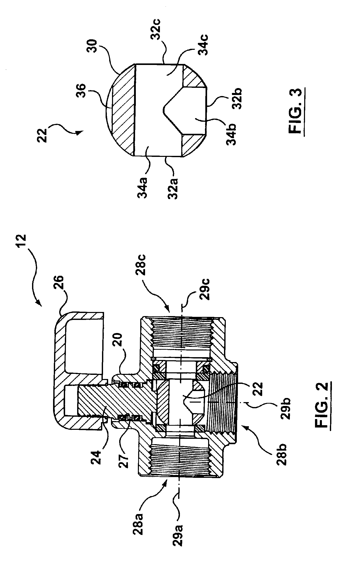
[0064]Referring now to FIG. 2, the valve body 12 comprises a valve housing 20 having a valve closure member 22. The valve body 12 further comprises a spindle 24, a valve handle 26, and three ports 28a, 28b, and 28c. The 3 ports have a common configuration and can accept any of the parts 14 of the kit of parts 10.

[0065]As shown in FIG. 3, the valve closure member 22 comprises a sphere 30 as is used in what is commonly known as a “ball valve”, but it is to be appreciated by one skilled in the art that any known valve closure member can be used to carry out the present invention.

[0066]The sphere 30 comprises three openings 32a, 32b, and 32c leading to channels 34a, 34b, and 34c, respe...


PUM


Abstract

A kit of parts for configuring and assembling a shut-off valve in the field has a valve body, a plurality of connection fittings, and a plurality of gaskets. The connection fittings each have a first end with a common configuration adapted to fit into any of three ports provided in the valve body. The connection fittings have second ends with different configurations adapted to connect with any of a variety of conduit configurations which may be encountered in the field.

Description

RELATED APPLICATIONS[0001]The following is a Continuation-in-part Application to U.S. patent application Ser. No. 10 / 135,850, filed on May 1, 2002 now U.S. Pat. No. 6,874,824.FIELD OF THE INVENTION[0002]The present invention relates to valves used in fluid conduit configurations to alternately shut off or allow fluid flow.BACKGROUND OF THE INVENTION[0003]Providing fluid flow through a conduit is a common requirement. In industrial applications, the flow of air, water or other fluids is often required in the operation of equipment. In residential settings, household plumbing is probably the most common example of fluid flow in a conduit. In these applications, it is often desirable to have the ability to control the flow of fluid at one or more points, through the use of shut-off valves. Such valves can be used simply as an outlet for the fluid, or to isolate downstream elements for such purposes as repair or maintenance.[0004]The conduits to which a valve is to be connected will hav...

Claims


Application Information

Patent Timeline
Patent Type & Authority Patents(United States)
IPC IPC(8): F16K27/06F16K11/087F16K11/02
CPCF16K11/0876F16K27/067Y10S285/917Y10T137/86871Y10T137/5283
Inventor ANDERSON, GAYLENBANSA, PATRICE B.ZENGA, ANTONIOCHARRON, CHARLES S.HUSEBYE, TRYGVE
Owner DAHL BROS CANADA
Why Eureka
Try Eureka