Treatment of tissue in sphincters, sinuses and orifices
What is AI technical title?
AI technical title is built by Patsnap AI team. It summarizes the technical point description of the patent document.
a tissue and sphincter technology, applied in the field of tissue treatment, can solve the problems of high cost, high cost, and high invasiveness of methods, and achieve the effects of reducing the risk of iatrogenic effect, and improving the quality of li
Inactive Publication Date: 2006-04-04
NOVASYS MEDICAL
View PDF16 Cites 355 Cited by
Summary
Abstract
Description
Claims
Application Information
AI Technical Summary
This helps you quickly interpret patents by identifying the three key elements:
Problems solved by technology
Method used
Benefits of technology
Benefits of technology
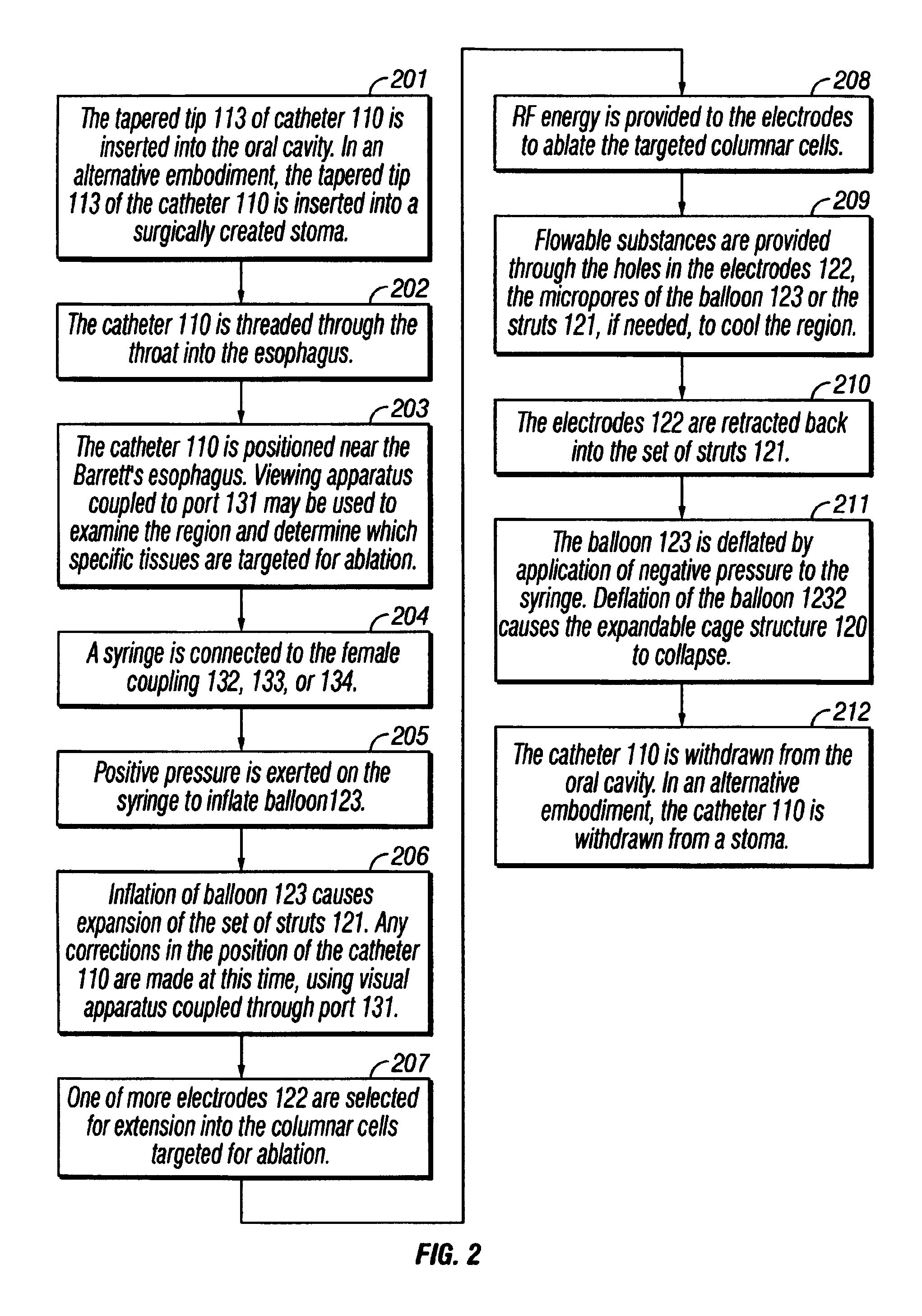
[0023]In one aspect of the invention, an environment proximate to or surrounding the targeted treatment region can be isolated or controlled by blocking the flow of gases or liquids using an inflatable balloon positioned immediately adjacent to the tissue that is to be ablated. The inflatable balloon can also serve to anchor the catheter in place and prevent the catheter from being expelled from the body. The inflatable balloon can also insure that locally administered drugs remain in the area where most needed.
[0024]In a second aspect of the invention, positive pressure is used to inflate the balloon. Inflation of the balloon triggers the extension of at least one curvilinear electrode into the targeted tissue. Negative pressure deflates the air sac and helps retract the curvilinear electrodes so as to allow the catheter to be removed from the body without damaging adjacent body structures. Alternately, the electrode(s) can be extended or retracted from the tissue, independently from the act of inflation or deflation of the balloon.
[0025]In a third aspect of the invention, the electrodes are coupled to sensors that measure properties of the target region such as temperature and impedance. Measurement of these properties permits the use of feedback technique to control delivery of the RF energy and administration of fluids for cooling and hydrating the affected tissues. The electrodes can also be coupled to radiopaque markers to aid in flouroscopic positioning.
Problems solved by technology
These methods only occasionally achieve the goal of successful treatment of disorders in orifices, sphincters, esophagus and sinuses.
Moreover, these methods suffer from several drawbacks.
Drawbacks to surgical treatment include its highly invasive nature, associated risks, possible iatrogenic effects, and high cost.
Drawbacks to pharmaceutical and chemotherapeutic treatments include their relative ineffectiveness (particularly in the oral cavity and adjacent respiratory structures) and associated side effects.
Moreover, these approaches are contraindicated for many patients.
Drawbacks to lifestyle modification include relatively poor patient compliance and relative ineffectiveness.
Drawbacks to photodynamic therapy include its frequent unavailability and limited applicability.
Drawbacks to radiation include side effects such as exhaustion, radiation burns, chronic dry mouth and permanent distortion of the taste buds.
However, known systems using RF energy are still subject to several drawbacks.
One known problem is that it can be difficult to block the flow of bodily fluids and gases into an area of the body where tissue ablation is taking place.
Bodily fluids can dissipate and detrimentally absorb the energy to be applied to the tissue to be ablated.
A second known problem in the art involves directing and positioning the electrodes in the body cavity or orifice.
Difficulties in accurately positioning the electrodes in the target orifice detract from treatment.
Frequently, unhealthy tissue can remain unablated while healthy tissue is removed.
Difficulties in directing and positioning the electrodes are particularly problematic because one of the goals of treatment is to minimize collateral damage to healthy tissue and to completely ablate diseased tissue.
A third known problem in the art involves difficulty in the simultaneous use of complimentary technology.
Known systems do not provide for optimal, simultaneous use of auxiliary tools for visualization, feedback technology and drug administration.
Method used
Image
Click on the blue label to locate the original text in one second.
Reading with bidirectional positioning of images and text.
Examples
Embodiment Construction
System Elements
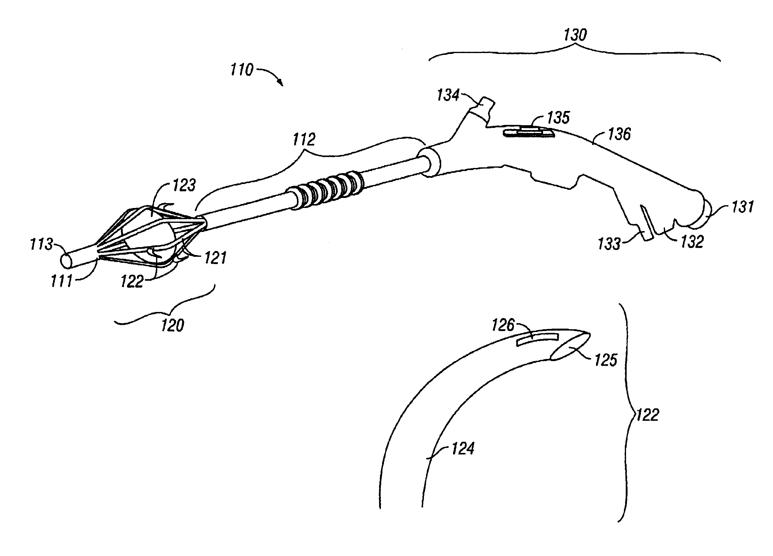
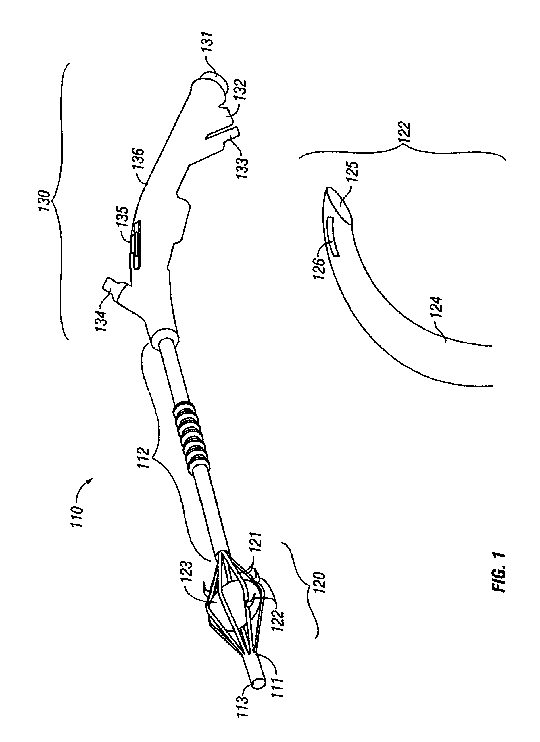
[0036]FIG. 1 is a block diagram of a system for ablating tissue associated with the rectal sphincter, esophagus, urethra and other internal body structures using a catheter and electrode assembly.
[0037]A catheter and electrode assembly 100 for treating tissue includes a catheter 110, an expandable cage structure 120 and a control and delivery linkage 130.
[0038]The catheter 110 includes a distal segment 111 and a proximal segment 112. The distal segment includes a tapered tip 113 for easy insertion into an orifice. The tapered tip 113 may be either flexible or rigid depending upon the orifice into which the catheter 110 is to be inserted. The overall length of the shaft of the catheter 110 (including the expandable cage structure 120) from the tapered tip 113 to the junction where the catheter 110 is coupled to the control and delivery linkage 120 is about 65 centimeters. The diameter of the catheter 110 is about 0.4 centimeters. In an alternative embodiment, the lengt...
PUM
Abstract
The invention provides a method and system for ablation of body structures or tissue in a sphincter, sinus or orifice such as the rectum, colon, esophagus, vagina, penis, larynx or pharynx. In one aspect of the invention, the environment surrounding the targeted ablation region can be isolated or controlled by blocking the flow of gases or liquids using an inflatable balloon positioned immediately adjacent to the tissue that is to be ablated. In a preferred embodiment, the inflatable balloon also serves to anchor the catheter in place and prevent the catheter from being expelled from the body. The inflatable balloon also insures that locally administered drug remain in the area where most needed. In a second aspect of the invention, positive pressure is used to inflate the balloon. Inflation of balloon triggers the extension of at least one curvilinear electrode into the targeted tissue. Negative pressure deflates the air sac and helps retract the curvilinear electrodes so as to allow the catheter to be removed from the body without damaging adjacent body structures. In a third aspect of the invention, the electrodes are coupled to sensors that measure properties of the target region such as temperature and impedance. Measurement of these properties permits the use of feedback technique to control delivery of the RF energy and administration of fluids for cooling and hydrating the affected tissues. In a fourth aspect of the invention, the catheter includes an optical path that can be coupled to external viewing apparatus. In this way, the position of the electrodes in the body can be determined by fluoroscopic or fiber optic techniques.
Description
[0001]This application is a Continuation-in-part of U.S. patent application Ser. No. 08 / 717,612, now U.S. Pat. No. 6,077,257, filed on Sep. 20, 1996, which is a Continuation-in-part of:[0002]U.S. patent application Ser. No. 08 / 677,811, filed Jul. 10, 1996, now U.S. Pat. No. 5,921,954;[0003]U.S. patent application Ser. No. 08 / 651,378, filed May 22, 1996, now U.S. Pat. No. 5,738,114;[0004]U.S. patent application Ser. No. 08 / 651,800, filed May 22, 1996, now U.S. Pat. No. 5,836,906;[0005]U.S. patent application Ser. No. 08 / 643,203, filed May 6, 1996, now U.S. Pat. No. 5,718,702;[0006]U.S. patent application Ser. No. 08,643,524, filed May 6, 1996, now U.S. Pat. No. 5,743,870;[0007]U.S. patent application Ser. No. 08 / 651,796, filed May 22, 1996, now abandoned;[0008]U.S. patent application Ser. No. 08 / 651,798, filed May 22, 1996, now abandoned;[0009]U.S. patent application Ser. No. 08 / 660,539, filed Jun. 7, 1996, now U.S. Pat. No. 5,743,904; and[0010]U.S. patent application Ser. No. 08 / 663...
Claims
Application Information
Patent Timeline
Application Date:The date an application was filed.
Publication Date:The date a patent or application was officially published.
First Publication Date:The earliest publication date of a patent with the same application number.
Issue Date:Publication date of the patent grant document.
PCT Entry Date:The Entry date of PCT National Phase.
Estimated Expiry Date:The statutory expiry date of a patent right according to the Patent Law, and it is the longest term of protection that the patent right can achieve without the termination of the patent right due to other reasons(Term extension factor has been taken into account ).
Invalid Date:Actual expiry date is based on effective date or publication date of legal transaction data of invalid patent.

