Jointed linkage system

a linkage system and joint technology, applied in the direction of turning machines, turning machine accessories, drawing profiling tools, etc., can solve the problems of cosmetic defects, wire breakage, limited ability of toys to bend in a somewhat random fashion,

Inactive Publication Date: 2005-08-23
C J ASSOCS
View PDF83 Cites 78 Cited by
  • Summary
  • Abstract
  • Description
  • Claims
  • Application Information

AI Technical Summary

Problems solved by technology

The traditional “bendable” toy has used flexible wire inserts to give the toy a limited ability to bend in a somewhat random fashion.
As a result of a number of play cycles in wire-supported bendable toys, the wire breaks.
That breakage may, in turn, lead to cosmetic defects and create safety problems in the form of sharp, protruding broken wire tips.
Safety: It has been difficult to solve the potential safety problems created by the sharp points formed on the ends of wire materials used as inserts for toy figures and the like.
The prior art metal-wire inserts do not offer this unique real-feel feature.
This need for flexibility of design creates a series of challenges.

Method used


Image

  • Jointed linkage system
  • Jointed linkage system
  • Jointed linkage system

Examples


Embodiment Construction

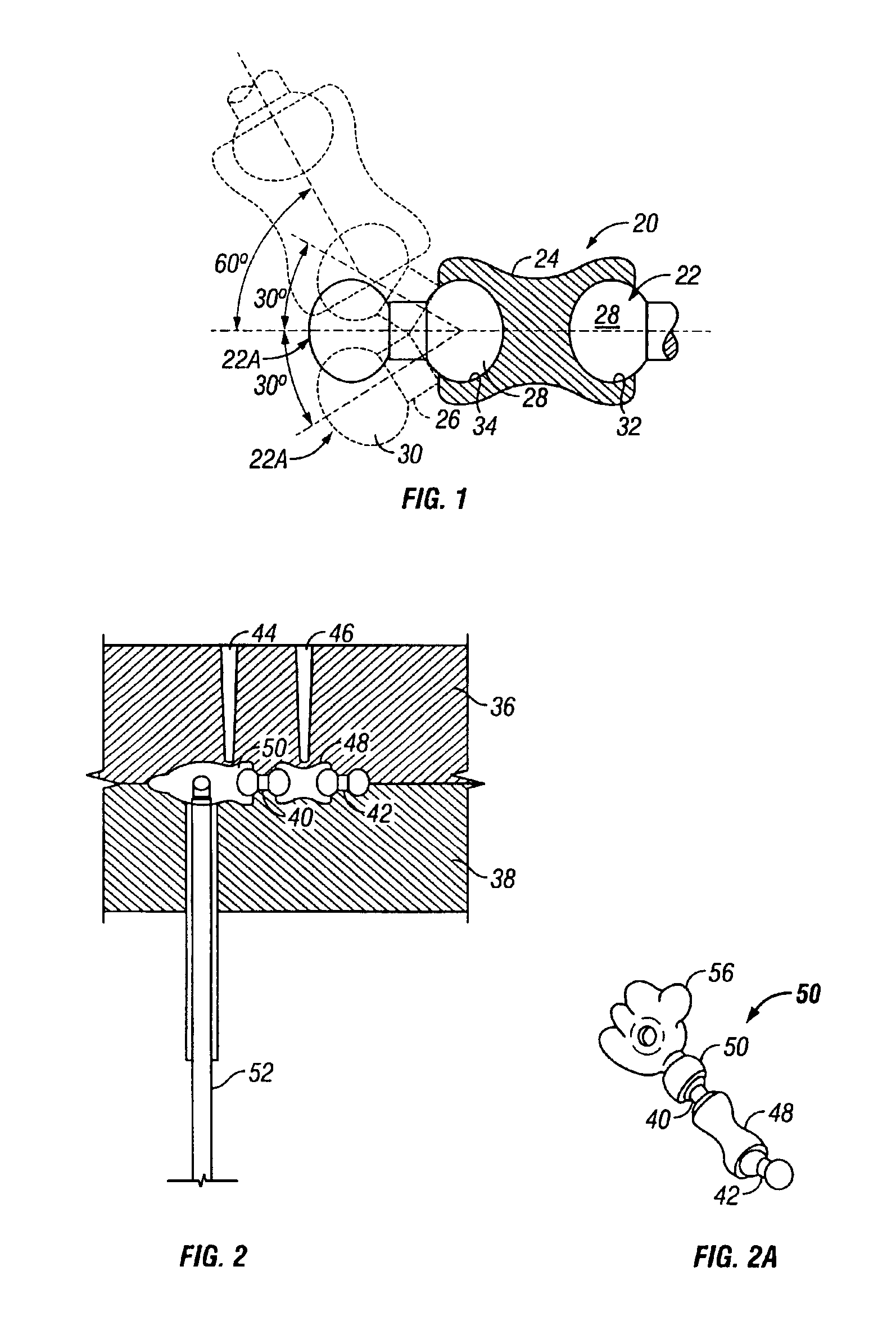
[0040]FIG. 1 shows the principles of a single flexible joint 20 having three parts, a pair of ball parts 22 and 22A in sockets 32 and 34 at opposite ends of a socket part 24. The ball parts each comprise a rod 26 with a ball 28, 30 on each end. The socket part 24 has cavities 32, 34 on each end. A ball of first ball part 22 is in socket 32 while a ball 28 of second ball part 22A is in socket 34.

[0041]The ball parts 22 and 22A are made from a first plastic having a relatively high melting temperature of from about 150° C. to 265° C. (and preferably about 175° C. to 265° C.). The socket parts 24 comprise a sleeve made from a second plastic having a lower melting temperature than the high melting temperature of the ball part 22 of from about 110° C. to 175° C. (and preferably about 130° C. to 175° C.). This way, the socket parts 24 may be molded with their sockets 32 and 34 encircling and retaining balls 28 and 30.

[0042]As the socket plastic cools, it shrinks to create a grip on the ba...


PUM

PropertyMeasurementUnit
angleaaaaaaaaaa
angleaaaaaaaaaa
melting temperatureaaaaaaaaaa

Abstract

A system for molding a jointed linkage support system with joints that allow movement and bending in many directions and degrees of freedom. A chain-like linkage system made up of a series of joints is molded in a single step from materials having different melting temperatures in a series of alternating communicating mold cavities. The jointed linkage support system emerges from the mold fully assembled. An electrical switch may be provided within one of the joints between sleeves and rods whereby movement of the rod relative to the sleeve actuates the switch.

Description

FIELD OF THE INVENTION[0001]This is a divisional of allowed U.S. patent application Ser. No. 09 / 665,031, filed Sep. 19, 2000, which is now U.S. Pat. No. 6,607,684, and hereby incorporated by reference.[0002]This invention relates to jointed linkage support systems and more particularly, but not exclusively, to support systems for toys having lifelike joints.BACKGROUND AND SUMMARY OF THE INVENTION[0003]There are many uses for a jointed linkage support system of the described type. The system may serve, for example, as a toy for making original geometric forms, or as a support for an object on display. However, a principal use of particular interest to the inventors is as a skeleton for a toy such as a doll, an animal, or the like. Toy animals and figures with movable necks, arms, legs, and spines may be made in many forms including skeletal figures, action figures, fashion dolls and stuffed animals covered in plush, simulated fur or vinyl.[0004]For any of these and many other uses, t...

Claims


Application Information

Patent Timeline
Patent Type & Authority Patents(United States)
IPC IPC(8): A63H3/46A63H3/00B29C45/14B29C45/00B29C65/00B29C65/66
CPCA63H3/46B29C45/14467B29C45/0017Y10T403/32631B29C2045/002B29L2031/5218B29C65/665
Inventor LEE, JAMES S. W.KWAN, CHIU-KEUNG
Owner C J ASSOCS
Why Eureka
Try Eureka