Liquid crystal display including an anisotropic scattering layer

a liquid crystal display and anisotropic scattering technology, applied in the field of single-polarizer reflective liquid crystal display, can solve the problems of difficult manufacturing process, low display brightness, shadows appearing on the display, etc., and achieve the effect of good viewing angle characteristi

Inactive Publication Date: 2005-08-23
CITIZEN WATCH CO LTD
View PDF14 Cites 25 Cited by
  • Summary
  • Abstract
  • Description
  • Claims
  • Application Information

AI Technical Summary

Benefits of technology

[0021]According to the present invention, in a single-polarizer liquid crystal display comprising a top polarizer, an optical compensating element, an anisotropic scattering layer, and a liquid crystal device incorporating therein a reflective layer, the anisotropic scattering layer is constructed so that light entering it is scattered over a wider angle along the preferential viewing angle direction (Y-axis direction) than along the direction (X-axis direction) oriented at right angles to the preferential viewing angle direction.
[0022]Further, the incident angle dependence of the straight-go transmittance of the anisotropic scattering layer is made symmetrical or asymmetrical about the layer normal

Problems solved by technology

This configuration, however, has the problem that not only is the low brightness of the display, but shadows appear on the display because the reflective layer is placed outside the glass substrate.
To address this, in one method it has been practiced to roughen the reflective electrode in order to enhance display brightness in other directions than the specular direction, but the problem is that this requires a difficult manufacturing process.
However, in the liquid crystal display provided with such a scattering layer, image blurring occurs if the degree of scattering of the scat

Method used


Image

  • Liquid crystal display including an anisotropic scattering layer
  • Liquid crystal display including an anisotropic scattering layer
  • Liquid crystal display including an anisotropic scattering layer

Examples


embodiment 1

[0065]FIG. 7 shows the configuration of a liquid crystal display according to a first embodiment. As shown in FIG. 7, the liquid crystal display comprises a liquid crystal device 20, an anisotropic scattering layer 10 formed on the upper side of the liquid crystal device 20, that is, the side nearer to the viewer and opposite from the side where a reflector is provided, a twisted phase film 12, a first retardation film 13, a second retardation film 14, and a top polarizer 11. In the present embodiment, three retardation films, that is, the twisted retardation film 12, the first retardation film 13, and the second retardation film 14, together constitute the optical compensating element.

[0066]The top polarizer 11, the second retardation film 14, the first retardation film 13, the twisted retardation film 12, and the anisotropic scattering layer 10 are laminated together using an acrylic adhesive, and the anisotropic scattering layer 10 is bonded to the liquid crystal device 20 by usi...

embodiment 2

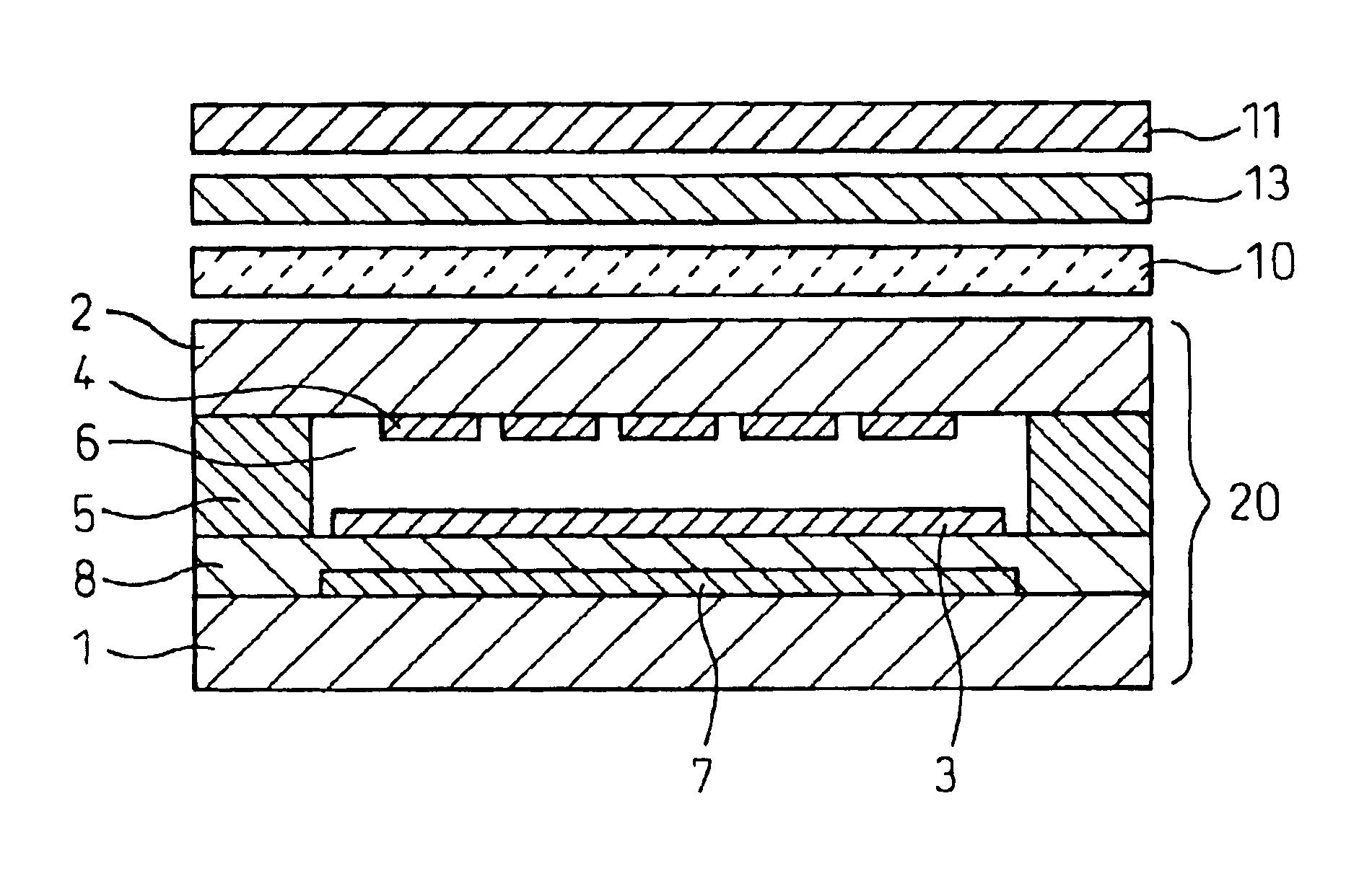
[0101]Next, a liquid crystal display according to a second embodiment of the present invention will be described below. The configuration of the liquid crystal display of the second embodiment is the same as that shown in FIG. 1. As shown in FIG. 1, the liquid crystal display includes the liquid crystal device 20, the anisotropic scattering layer 10 formed on the side nearer to the viewer than to the reflector, the retardation film 13 as the optical compensating element, and the top polarizer 11. The top polarizer 11, the retardation film 13, and the anisotropic scattering layer 10 are laminated together using an acrylic adhesive, and the anisotropic scattering layer 10 is bonded to the liquid crystal device 20 by using an acrylic resin.

[0102]The configuration of the liquid crystal device 20 is the same as that used in the first embodiment, and therefore, the description of it will not be repeated here.

[0103]The retardation film 13 is a transparent film about 70 μm in thickness form...

embodiment 3

[0123]A third embodiment of the present invention will be described below. The configuration of the liquid crystal display of this embodiment is the same as that shown in FIG. 1, and the configuration of the pixel section is the same as that shown in FIG. 8. Further, the relative orientations of the various component elements are the same as those shown in FIGS. 9 and 13.

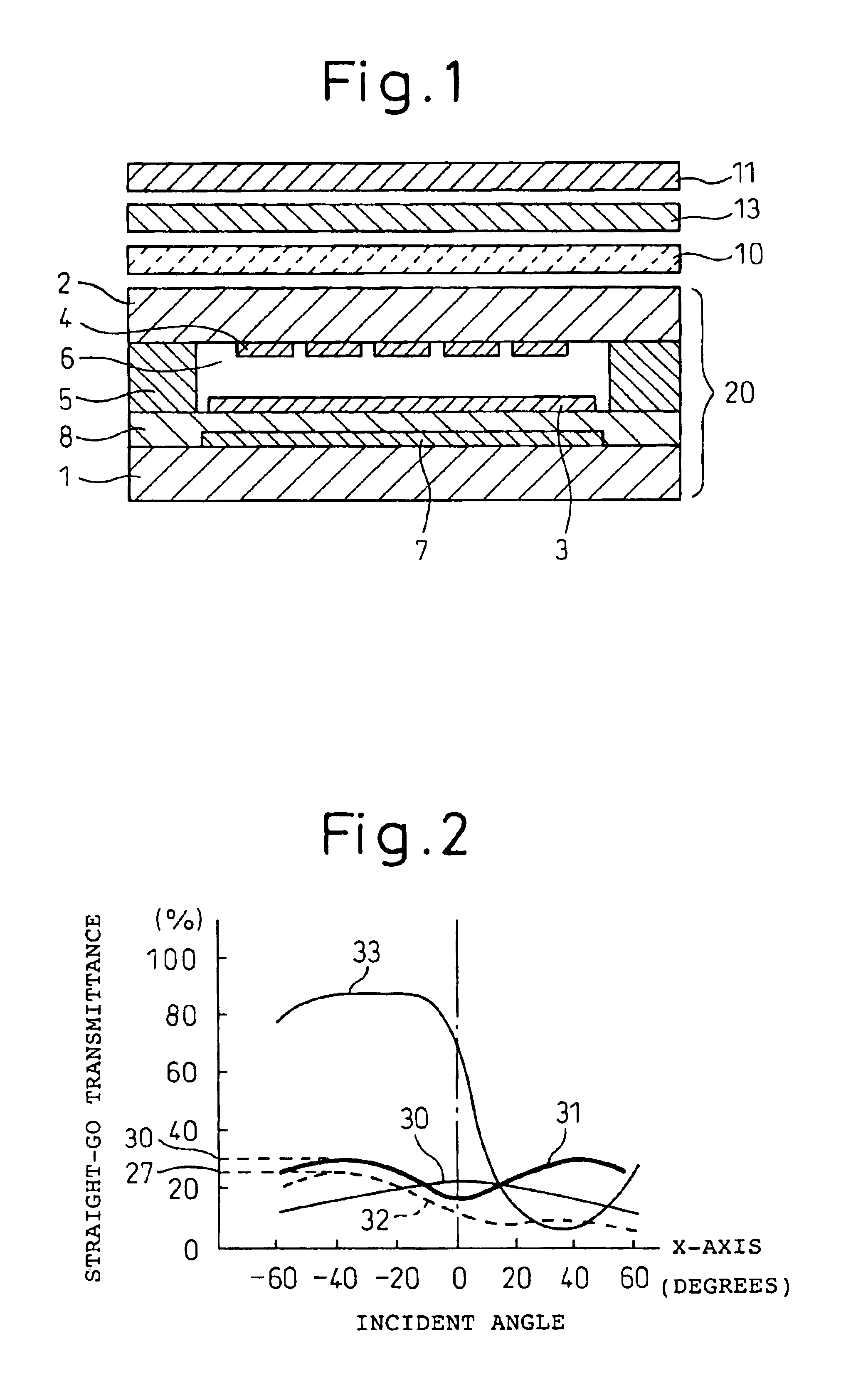
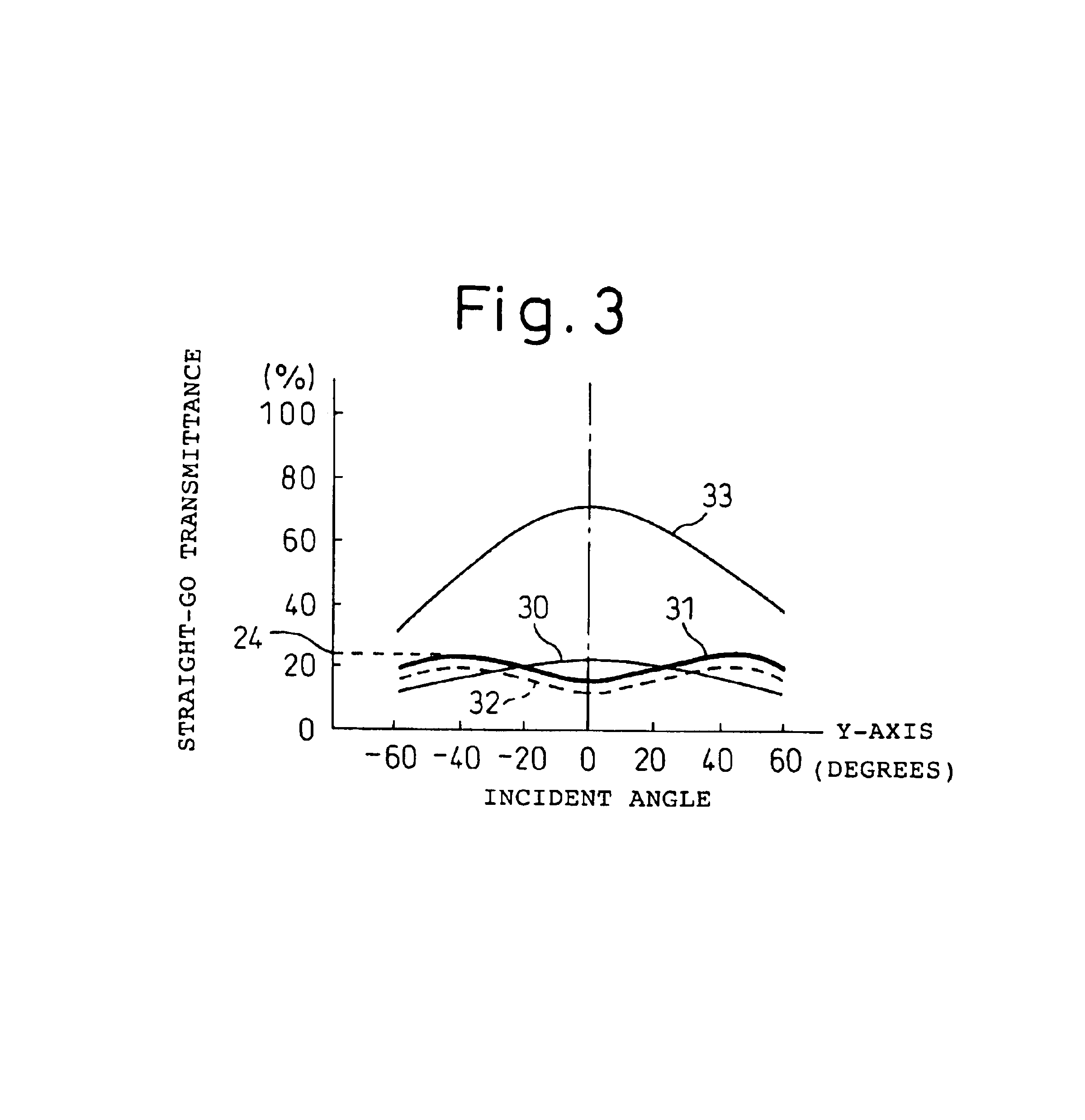
[0124]The difference of the liquid crystal display of this embodiment is that the anisotropic scattering layer having the incident angle dependence shown by the curve 34 in FIGS. 5 and 6 is used as the anisotropic scattering layer 10 in the configuration shown in FIG. 1.

[0125]As shown by the curve 34 in FIGS. 5 and 6, the anisotropic scattering layer used in this embodiment has the characteristic that, for both the X-axis and Y-axis directions, the incident angle dependence is the same and is symmetrical about the layer normal. In the case of the anisotropic scattering layer 10 used in the present embodiment and hav...


PUM


Abstract

A liquid crystal display comprises a top polarizer 11, an optical compensating element, an anisotropic scattering layer 10, a scattering layer 7, and a liquid crystal device 20 incorporating therein a reflective layer 9. When the direction of viewing direction of the anisotropic scattering layer is designated as the Y-axis direction, and a direction oriented substantially at right angles to the Y-axis direction is designated as the X-axis direction, light entering the anisotropic scattering layer is scattered over a wider angle along the Y-axis direction than along the X-axis direction. Further, the incident angle dependence of the straight-go transmittance of the anisotropic scattering layer is symmetrical about the layer normal, and the straight-go transmittance in the layer normal direction is lower than the straight-go transmittance in any oblique direction.

Description

TECHNICAL FIELD[0001]The present invention relates to the construction of a liquid crystal display, and more particularly to a single-polarizer reflective liquid crystal display which achieves a bright black and white or color display using a single polarizer and a internal reflector in a liquid crystal display device.BACKGROUND ART[0002]Conventionally, reflective liquid crystal displays have been constructed using a pair of polarizers, a reflective layer placed on the outside of one of the polarizers, and a TN (twisted nematic) or STN (super twisted nematic) liquid crystal device sandwiched between them. This configuration, however, has the problem that not only is the low brightness of the display, but shadows appear on the display because the reflective layer is placed outside the glass substrate.[0003]To address this problem, there has been proposed a single-polarizer reflective liquid crystal display that can produce a display using a single polarizer. Since only one polarizer ...

Claims


Application Information

Patent Timeline
IPC IPC(8): G02F1/1335G02F1/13G02F1/13363
CPCG02F1/133504G02F1/133555G02F1/13363G02F2203/02G02B5/0236G02B5/0257G02F1/1335
Inventor KANEKO, YASUSHIARAI, MAKOTO
Owner CITIZEN WATCH CO LTD
Why Eureka
Try Eureka