
Cable trough cover

a technology of troughs and covers, applied in the installation of lighting conductors, instruments, manufacturing tools, etc., can solve the problems of system inability to adapt to changes in customer needs, and inapplicability of routing systems

Inactive Publication Date: 2005-08-23
COMMSCOPE TECH LLC
View PDF54 Cites 79 Cited by
  • Summary
  • Abstract
  • Description
  • Claims
  • Application Information

AI Technical Summary

Benefits of technology

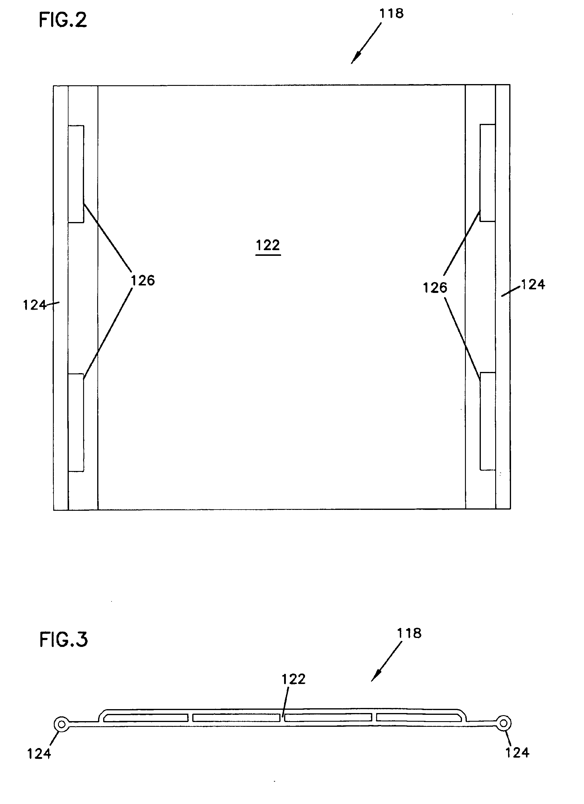
[0012]Yet another aspect of the present invention relates to a cable trough assembly including a cable trough, two cover plates, and two hinge pieces. The cover plates include pivot members along at least one edge. The hinge pieces are positioned on sidewalls of the trough. The hinge pieces each define pockets which releasably receive the pivot members of the cover plates so that the cover plates may be rotated relative to the trough.

Problems solved by technology

Accordingly a routing system is not practical which would require a high capital outlay and which could not be readily adapted to changes in a customer's needs.
Namely, if routing paths, once established, are forever fixed, the system cannot adapt.

Method used


Image

  • Cable trough cover
  • Cable trough cover
  • Cable trough cover

Examples


Embodiment Construction

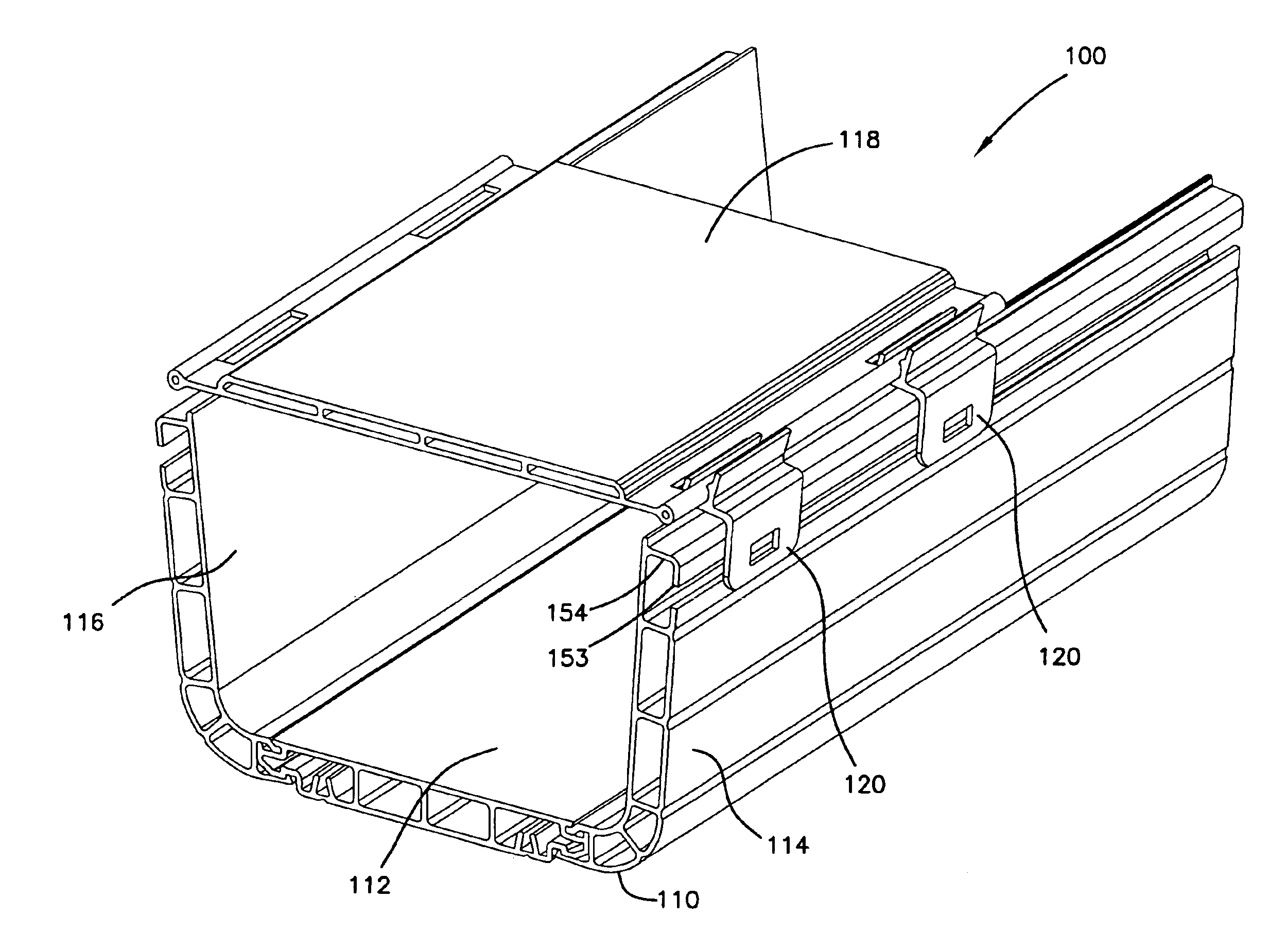
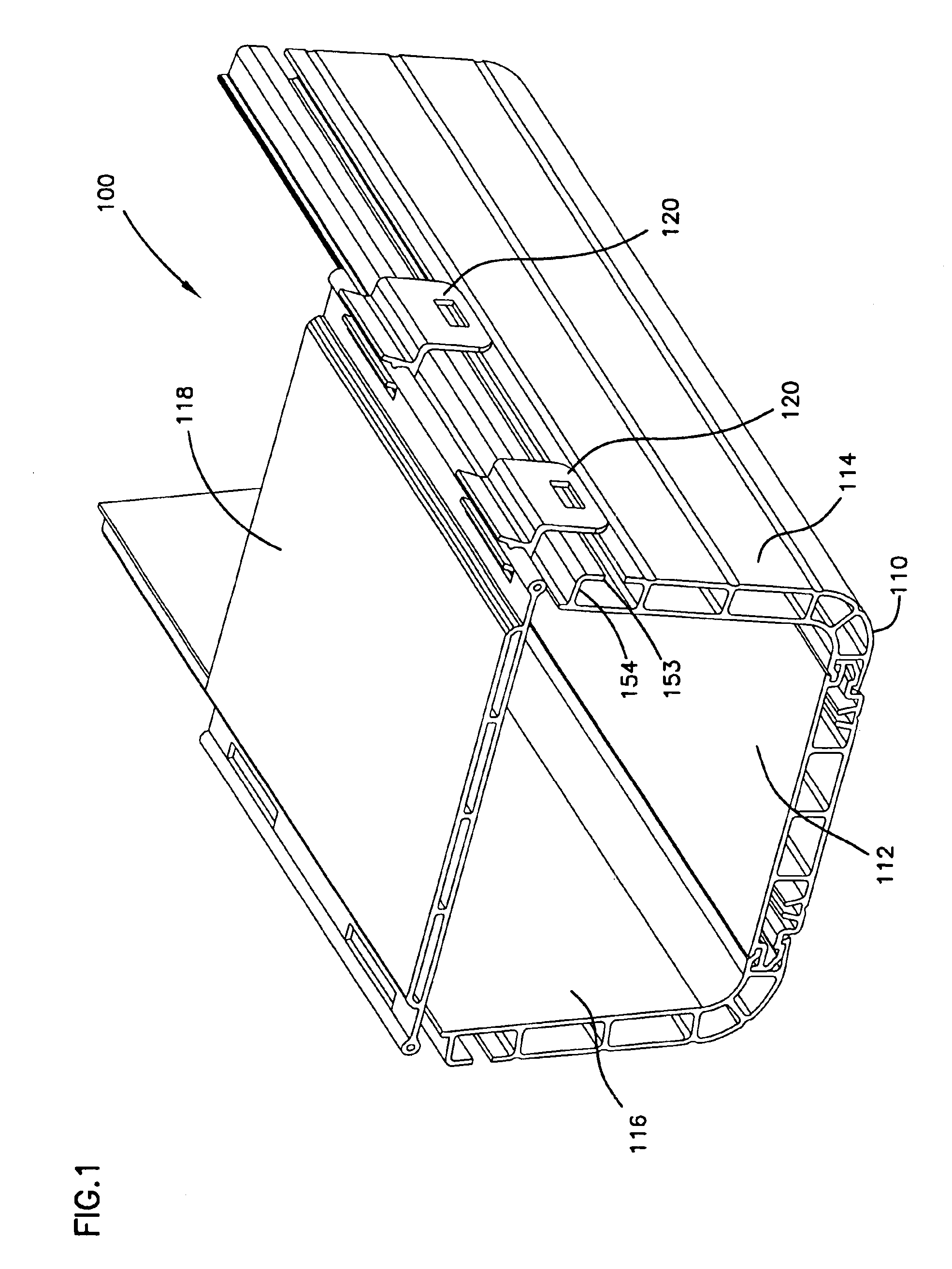
[0031]Referring now to FIG. 1, cable trough assembly 100 is shown which includes a cable trough 110 having a base 112 and two sidewalls 114 and 116. The assembly further includes a cover plate 118 and hinge pieces 120. Hinge pieces 120 straddle sidewall 114 and receive cover plate 118 so that a hinged joint is formed between the cover plate 118 and the hinge pieces 120.

[0032]The assembly 100 of the present invention allows the cover plate 118 to be snap-fit into the hinge pieces 120 and adjustably positioned in open and closed positions relative to the cable trough 110. For instance, the cover plate may be laid in a closed position over the cable trough to protect cables inside the trough. The cover plate 118 may then be conveniently pivoted by means of the hinge joint into an open position to allow access to the trough interior. Because the cover plates are snap-fit into the hinge pieces, the cover plate may be easily removed from or added to the assembly without the need for time ...


PUM


Abstract

A cable trough cover assembly and method of assembly including a cover plate and a hinge piece. The cover plate includes a pivot member along at least one edge, and the hinge piece defines a pocket for releasably receiving the pivot member. The pocket and pivot member arrangement allow the cover plate to be rotated relative to a cable trough to which the hinge pieces may be mounted.

Description

CROSS REFERENCE TO RELATED APPLICATIONS[0001]This application is a continuation of application Ser. No. 09 / 910,418, filed Jul. 20, 2001 now U.S. Pat. No. 6,810,191, which application is incorporated herein by reference.FIELD OF THE INVENTION[0002]The invention pertains to systems for the management and routing of optical fiber cables and other cables.BACKGROUND OF THE INVENTION[0003]In the telecommunications industry, the use of optical fibers for signal transmission is accelerating. With the increased utilization of optical fiber systems, optical fiber cable management requires industry attention. Other telecommunications cables, including copper-based cables benefit from increased attention on cable management.[0004]One area where cable management is necessary is the routing of cables from one piece of equipment to another. For example, in a telecommunications facility, optical fiber cables may be routed between fiber distribution equipment and optical line terminating equipment. ...

Claims


Application Information

Patent Timeline
Patent Type & Authority Patents(United States)
IPC IPC(8): G02B6/44H02G3/04
CPCG02B6/4459H02G9/04H02G3/0418Y10T16/5329
Inventor FERRIS, MATTHEW D.FISHER, JOEL T.
Owner COMMSCOPE TECH LLC
Learn More