Weapon aiming system

Inactive Publication Date: 2005-08-30
NEXTER SYST SA
View PDF21 Cites 4 Cited by
  • Summary
  • Abstract
  • Description
  • Claims
  • Application Information

AI Technical Summary

Benefits of technology

[0016]The aim of the present invention is to produce a laying system for a weapon mounted on a mobile carrier allowing pre-stabilising motorization to separate the motorization dimensioning need occasioned by the off-centring of the weapon from that privileging the quality of the orientation control.
[0022]According to yet another characteristic, the weapon is mounted able to rotate with respect to the clamp, the second positioning means ensuring the rotation of the weapon with respect to the clamp around the second axis.
[0030]Another advantage lies in the reduction of parasitic torques between the weapon and the clamp.

Problems solved by technology

When a weapon is mounted on a mobile support, that is on a moving vehicle, its laying operations become very difficult to ensure since the weapon is subject to a certain number of disturbances.
When the off-centring between the axial position of the centre of gravity and the rotational axis increases, the performances obtained rapidly deteriorate through a combination of several mechanisms.
First of all, the off-centring of the centre of gravity increases the effect of the vertical acceleration produced (the unbalance effect) when travelling on the angular displacement of the weapon.
The increase in the motorization torque requirement caused by the dynamic torque requirement (in spite of the static equilibrating of the unbalance mass) leads in particular to the increase in inertia of the motor.
On certain weapon systems, functional constraints in particular related to the feeding principle of the weapon add to the off-centring of the centre of gravity of the geometric constraints that increase the friction at the trunnions with its effect on the orientation accuracy of the weapon.
Lastly, on other systems, to minimise the necessary volume at the rear and under the axis of orientation of the weapon, the assembly of this weapon requires the axis of orientation to be largely pushed back to the rear of the recoiling mass, this results in a substantial increase in the off-centring with its effect of the orientation accuracy, in particular during travel.

Method used


Image

  • Weapon aiming system
  • Weapon aiming system
  • Weapon aiming system

Examples


Embodiment Construction

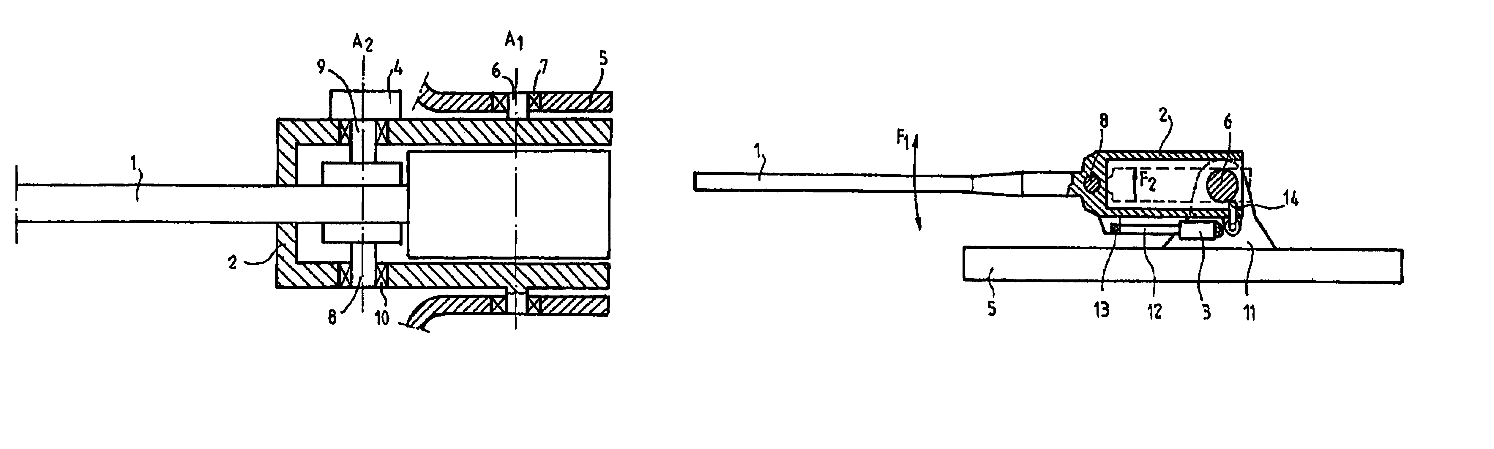
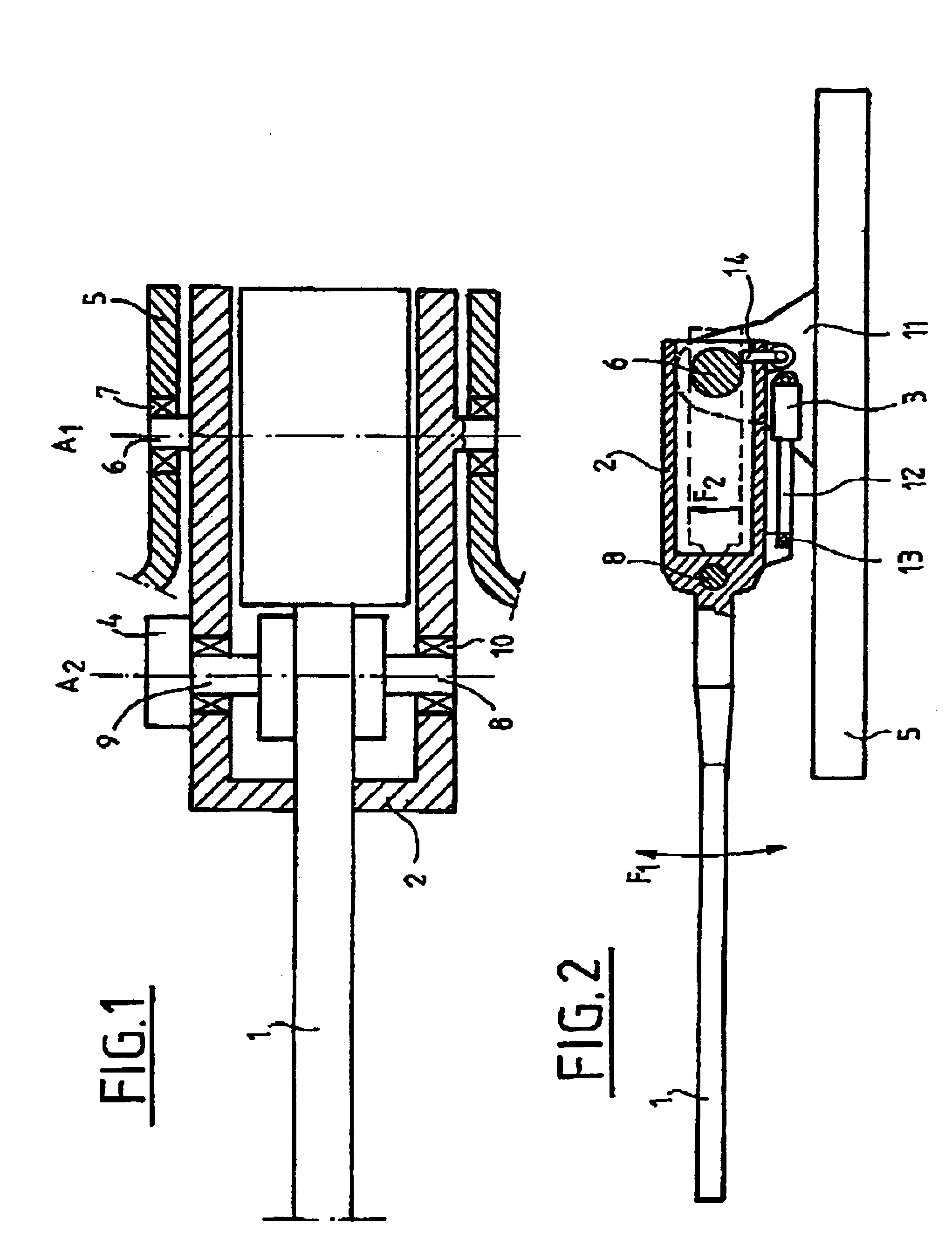
[0037]As is apparent from the above, the invention consists in providing two motorizations of the weapon with respect to its support. A first motorization, or main motorization, allows the weapon to be roughly oriented in elevation. This motorization allows the weapon to be positioned without any constraints. A second motorization allows the orientation of the weapon to be finely adjusted taking its bearing the main motorization. The advantage of such a system lies in the fact that the range between the weapon and the clamp is limited to stabilisation errors, thereby making it simple to produce. Moreover, since the dimensioning of the second motorization is linked only to the inertia of the weapon to be oriented, efficient torque control is carried out with any specific constraints.

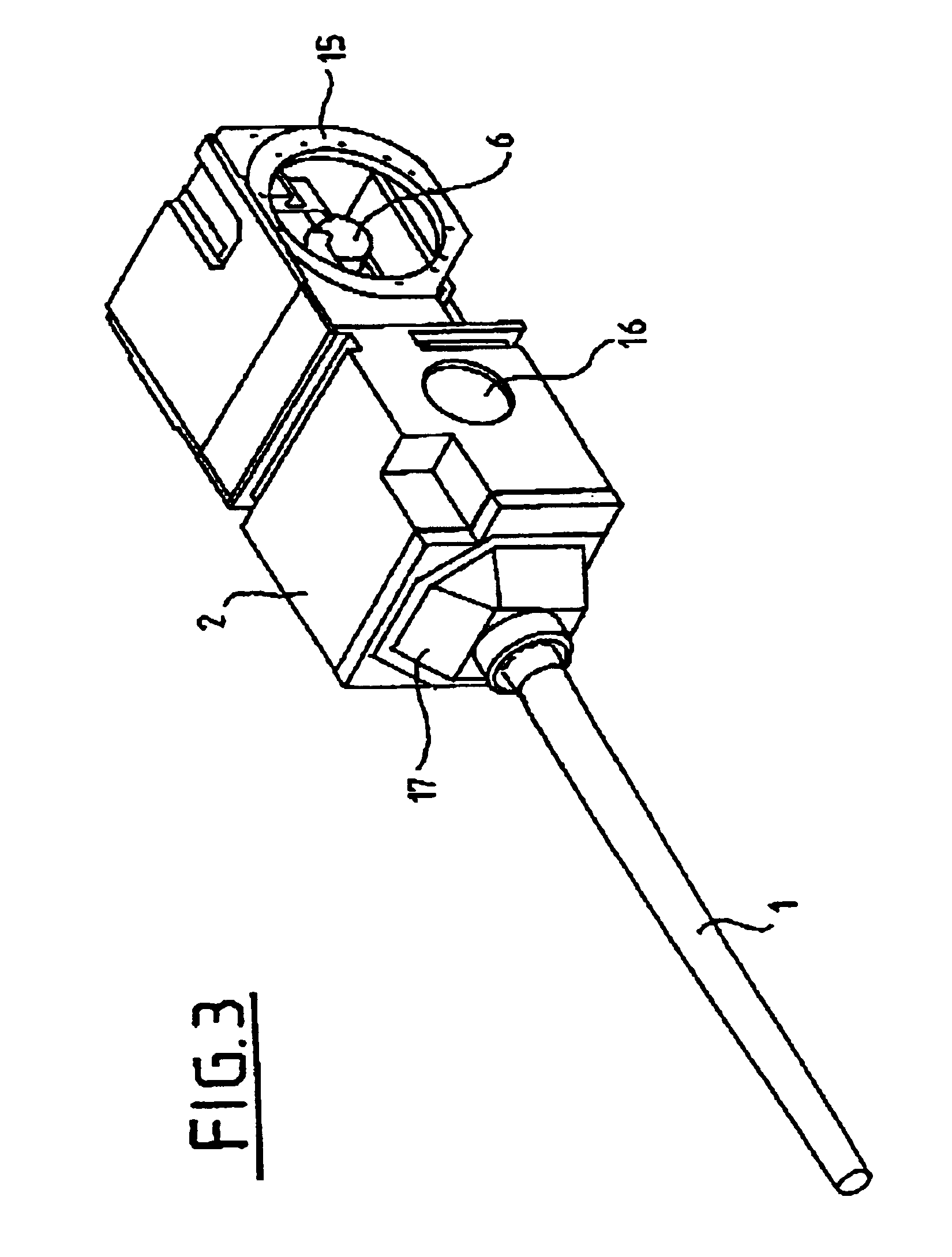
[0038]FIG. 1 shows the weapon 1 to be oriented in elevation made integral with a clamp 2 itself mounted able to rotate with respect to a support 5, for example a turret, by means of trunnions 6 and bearin...


PUM


Abstract

The invention relates to an elevation laying system for a weapon mounted on a vehicle.It comprises first positioning means for the weapon along a wide elevation range with respect to a first axis of rotation offset with respect to the center of gravity of the weapon, and second positioning means for the weapon connected to the first means along a narrow elevation range with respect to a second axis of rotation passing through the center of gravity of the weapon. The first axis of rotation is located to the rear of the weapon's center of gravity. The first positioning means are hinged with respect to a frame onto which the weapon is mounted around the first axis of rotation.

Description

BACKGROUND OF THE INVENTION[0001]The technical scope of the present invention is that of laying systems for a weapon that ensure its stabilisation.[0002]When a weapon is mounted on a mobile support, that is on a moving vehicle, its laying operations become very difficult to ensure since the weapon is subject to a certain number of disturbances. Firing from such a weapon requires it to be oriented in the direction of the target despite any movement be it linear or angular of the vehicle. One particularity of a vehicle able to move at high speeds (over 50 Km / H) cross country lies in the stresses to which it subjects the weapon and its laying system and which generally correspond to a high frequency level and cover a wide spectrum.[0003]During travelling, these disturbances may come from:[0004]the angular velocity of the support on which the weapon is mounted in traverse and that is located on the weapon at the motorization system,[0005]the linear acceleration applied to the trunnions ...

Claims


Application Information

Patent Timeline
IPC IPC(8): F41A27/24F41A27/00F41A27/08F41G5/24F41G5/00
CPCF41A27/08F41A27/24F41G5/24
Inventor URVOY, EMILE
Owner NEXTER SYST SA
Why Eureka
Try Eureka