High capacity globe valve

a globe valve, high-capacity technology, applied in the direction of engine components, mechanical equipment, transportation and packaging, etc., can solve the problems of limiting the overall flow efficiency of the valve, affecting the characteristics of the throttling control, and loss in the valve area, so as to reduce the loss of inertial flow, reduce the loss of fluid separation, and increase the annular volume

Inactive Publication Date: 2005-08-30
DRESSER LLC
View PDF114 Cites 35 Cited by
  • Summary
  • Abstract
  • Description
  • Claims
  • Application Information

AI Technical Summary

Benefits of technology

[0010]An advantage of the invention is that the offset throttling cage allows more annular volume between the throttling cage and the cavity walls in which to more gradually expand or contract flows through the throttling cage. This more gradual expansion or contraction reduces fluid separation from the cavity walls and turbulent flow mixing that causes fluid drag.
[0011]Another advantage of the invention is that the angled flow ports reduce inertial flow losses as the flow impinges on the cavity wall, because the flow directional changes within the valve are made more gradually.
[0012]Another advantage of the invention is that the flow ports can pass straight through the throttling cage and are thus less expensive to manufacture than curved flow ports and require a thinner throttling cage wall thickness to achieve the same directional change.
[0013]These and other advantages will be apparent from the following detailed description with reference to the following drawings.

Problems solved by technology

The convoluted flow causes flow losses in areas of the valve that are not controlled by the throttling cage and plug.
Not only do the losses limit the overall flow efficiency of the valve, but because they are independent of the flow throttling, the losses impact the characteristics of the throttling control.
Unfortunately, larger components such as a larger valve body and a larger throttling cage and plug that would result from the larger fluid ports, also increase the weight and cost of the valve.
Further, such larger components also require stronger and more expensive mechanisms, for example the mechanism on which the plug reciprocates.
These dimensions limit the extent to which the size of the valve body and other components can be increased.

Method used


Image

  • High capacity globe valve
  • High capacity globe valve
  • High capacity globe valve

Examples


Embodiment Construction

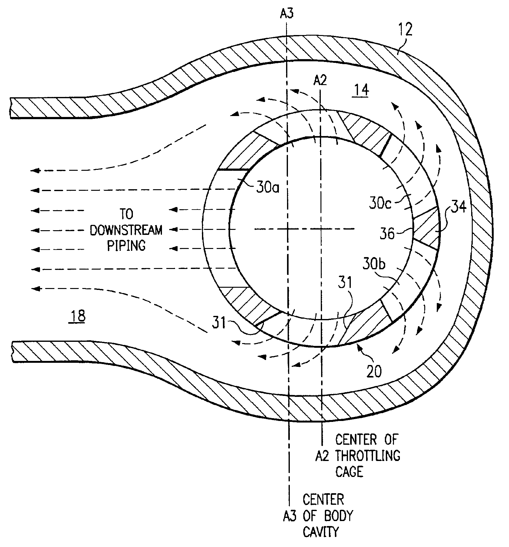
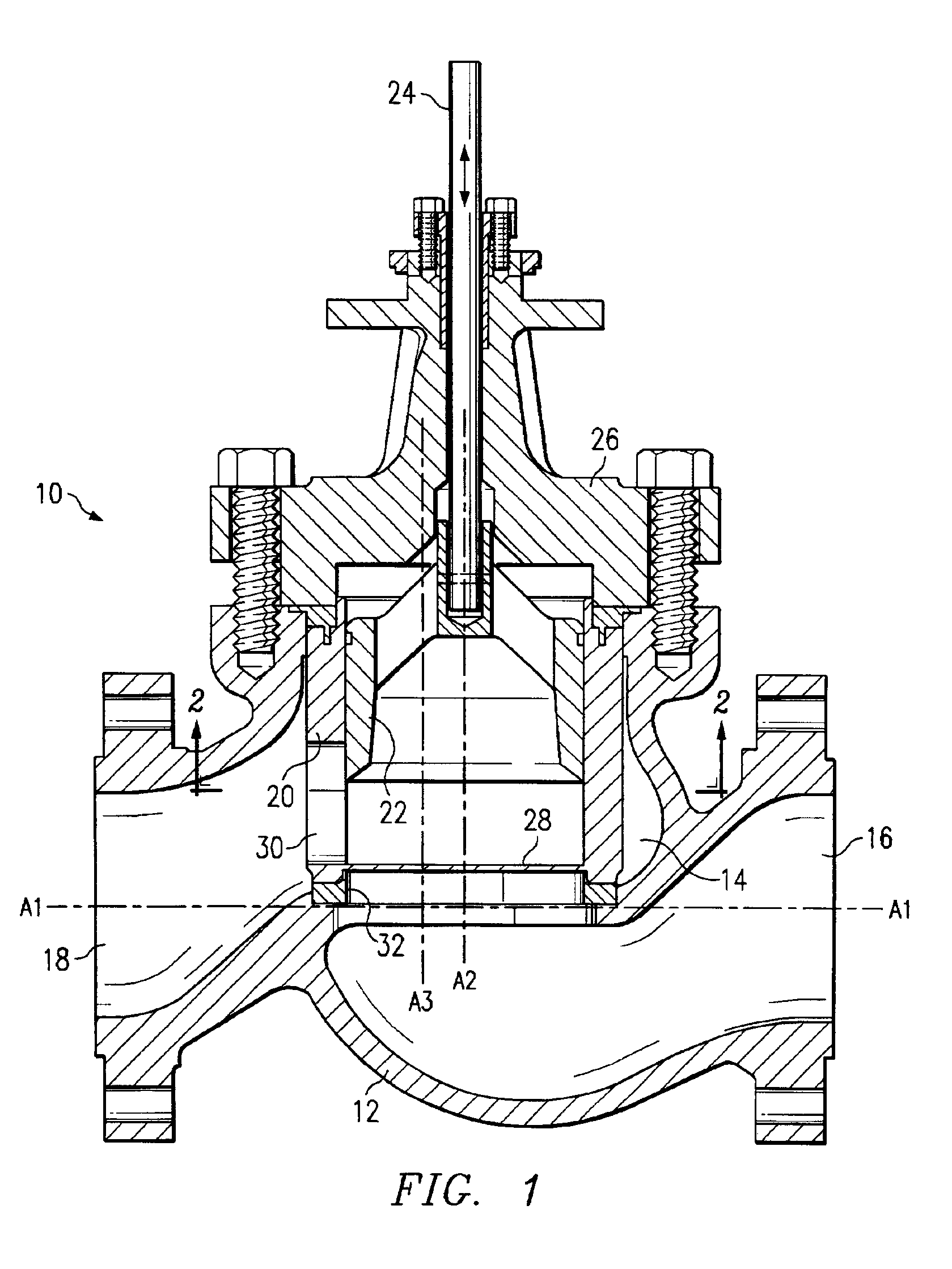
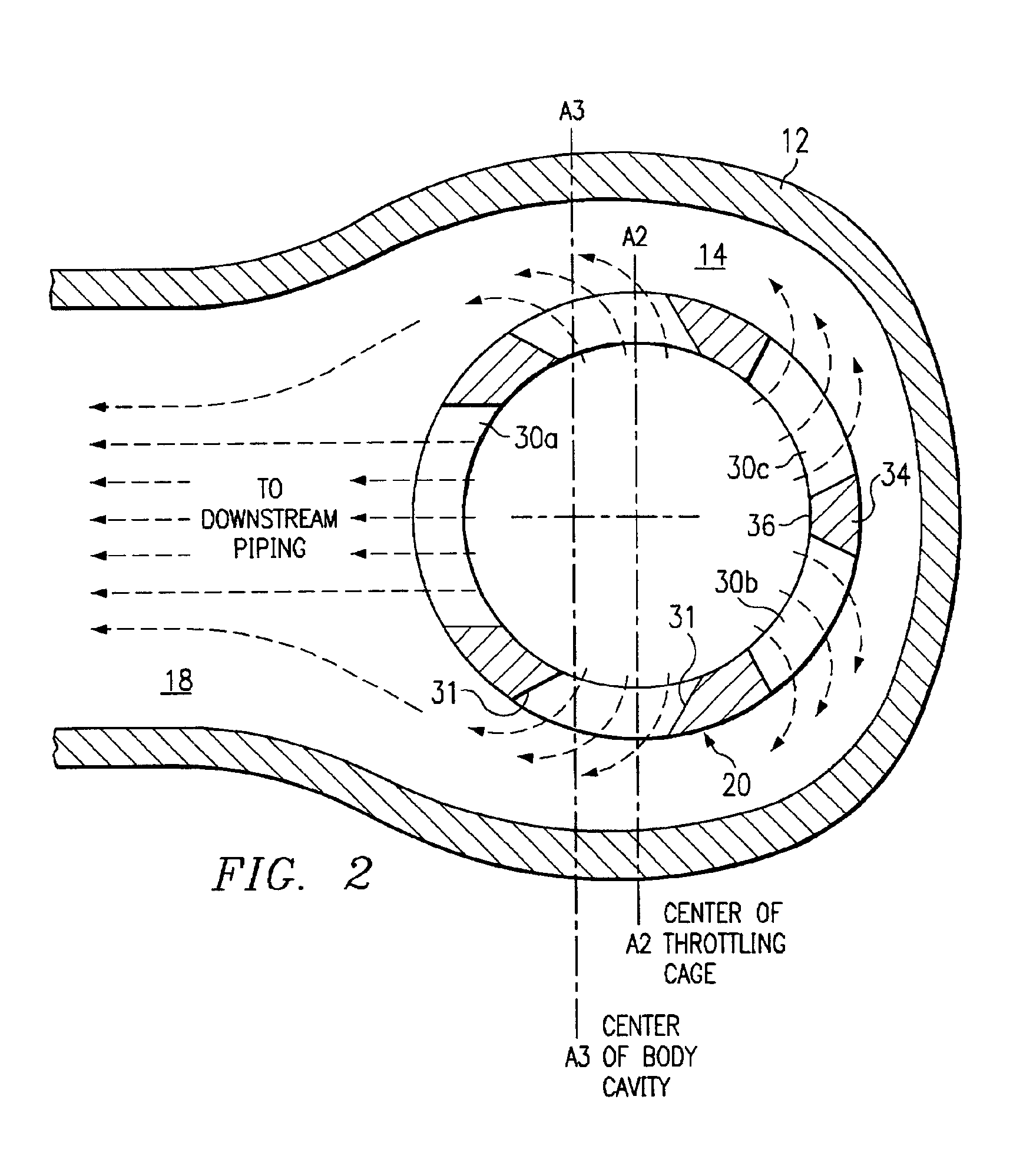
[0017]Referring first to FIG. 1, a globe valve 10 constructed in accordance with the invention has a flow body 12. Flow body 12 defines an interior cavity 14 in communication with an first fluid passage 16 and a second fluid passage 18. In the exemplary embodiment of FIG. 1, the first fluid passage 16 intersects a bottom of the cavity 14 near its center and the second fluid passage 18 intersects a side wall of the cavity 14. The interior of flow body 12 is contoured, so that fluid flows smoothly between the first fluid passage 16 and the second fluid passage 18. Further, the flow body 12 depicted in FIG. 1 is that of an inline configuration where, at opposite ends of the valve 10, the first fluid passage 16 and the second fluid passage 18 are substantially centered about the same axis A1. Fluid can travel through the valve 10 in either direction, from the first fluid passage 16 to the second fluid passage 18 or from the second fluid passage 18 to the first fluid passage. However, th...


PUM


Abstract

A high flow globe valve with a body defining an interior cavity in communication with a first and second fluid passages. A tubular throttling cage is offset in the cavity away from the second fluid passage and has an open end in communication with the first fluid passage. The throttling cage has flow ports angled towards the second fluid passage and the flow port nearest the second fluid passage is oversized. The throttling cage has flow splitter defined by two adjacent flow ports through the cage opposite the second flow passage. A plug is closely received in the throttling cage and moveable to cover the flow ports thereby restricting flow through the throttling cage.

Description

BACKGROUND OF THE INVENTION[0001]1. Technical Field of the Invention[0002]The present invention relates to high capacity valves, and more particularly to a globe valve configured to reduce flow losses and increase fluid flows therethrough.[0003]2. Description of Related Art[0004]In a globe valve, flow between a first fluid passage and a second fluid passage is controlled by a plug movable within a tubular throttling cage. Fluid flowing from the first passage to the second passage flows into the throttling cage through an open end, and out of the throttling cage through a plurality of radially oriented flow ports. Alternately, fluid flowing from the second passage to the first flows into the throttling cage through the radial flow ports and out the open end to the first passage. In either case, the plug is movable to selectively cover the flow ports, thereby restricting flow through the throttling cage and the valve.[0005]The flow path through a globe valve is convoluted. In an examp...

Claims


Application Information

Patent Timeline
Patent Type & Authority Patents(United States)
IPC IPC(8): F16K3/24F16K3/00
CPCF16K3/24Y10T137/86799Y10T137/86791
Inventor STARES, JAMES A.
Owner DRESSER LLC
Why Eureka
Try Eureka