Stator and torque converter containing the same

a technology of torque converter and torque converter, which is applied in the direction of machines/engines, belts/chains/gearrings, and machine/engine parts, etc., can solve the problems of reducing the efficiency of torque converter, generating fluid losses, and overall performance deterioration, so as to improve the overall torque converter efficiency, reduce fluid losses, and improve the effect of fluid flow

Active Publication Date: 2015-10-06
FCA US
View PDF28 Cites 2 Cited by
  • Summary
  • Abstract
  • Description
  • Claims
  • Application Information

AI Technical Summary

Benefits of technology

[0005]The present disclosure broadly comprises a stator designed to allow superior fluid flow and increase overall torque converter efficiency. The stator according to an aspect of the present invention contains a plurality of blades that have non-ruled surfaces. This unique shape of the blades assists in reducing fluid losses by improving the geometry of the channels through which the fluid within the stator flows.
[0006]The stator blades extend from an inner circumference of the stator to an outer circumference of the stator, and direct the flow of the fluid leaving the turbine output and entering the impeller input. In comparison to traditional stator blade designs that utilize linear edges and ruled-surfaces, the stator blades according to an aspect of the present invention have non-linear leading and trailing edges between the inner circumference and the outer circumference of the stator. Non-linear edges give the stator blades non-ruled surfaces which serve to decrease fluid separation from the blade surfaces. This decreases fluid losses and, in-turn, increases torque converter efficiency by providing an increased fluid flow rate within torque converter.
[0010]In yet another embodiment of the present invention, the torque converter contains non-ruled impeller blades and turbine blades usable with the stator of the present invention. In comparison to traditional blade designs that utilize ruled blade surfaces, non-ruled impeller and turbine blades serve to increase the flow rate of the fluid through the channels created by adjacent blades, and therefore further decrease fluid losses within the torque converter.
[0011]In yet another embodiment of the present invention, the torque converter contains a thrust washer usable with the stator of the present invention, wherein the thrust washer contains at least one groove on its front surface, and the front surface is curved such that the thickness of the thrust washer at the inner diameter is greater then the thickness of the thrust washer at the outer diameter. In comparison to traditional thrust washer designs, the present design increases the length of the at least one groove, allowing for a greater reduction in the velocity of the fluid traveling through the groove which, in turn, lessens fluid turbulence and further increases the fluid flow rate within the torque converter.
[0012]In yet another embodiment of the present invention, the thrust washer includes at least one groove having a width that is greater at the outer diameter of the thrust washer than at a point proximal to the inner diameter of the thrust washer. This creates a wider entry area to further increase the fluid flow rate within the torque converter.

Problems solved by technology

As the fluid travels through the channels created by the blades of a traditional torque converter, fluid losses are generated when the fluid flow becomes turbulent.
Fluid losses lead to overall performance deterioration and decreased torque converter efficiency.
Decreasing the overall dimensions of a torque converter decreases the size of the channels created by the blades, further increasing the buildup of fluid losses.

Method used


Image

  • Stator and torque converter containing the same
  • Stator and torque converter containing the same
  • Stator and torque converter containing the same

Examples


Embodiment Construction

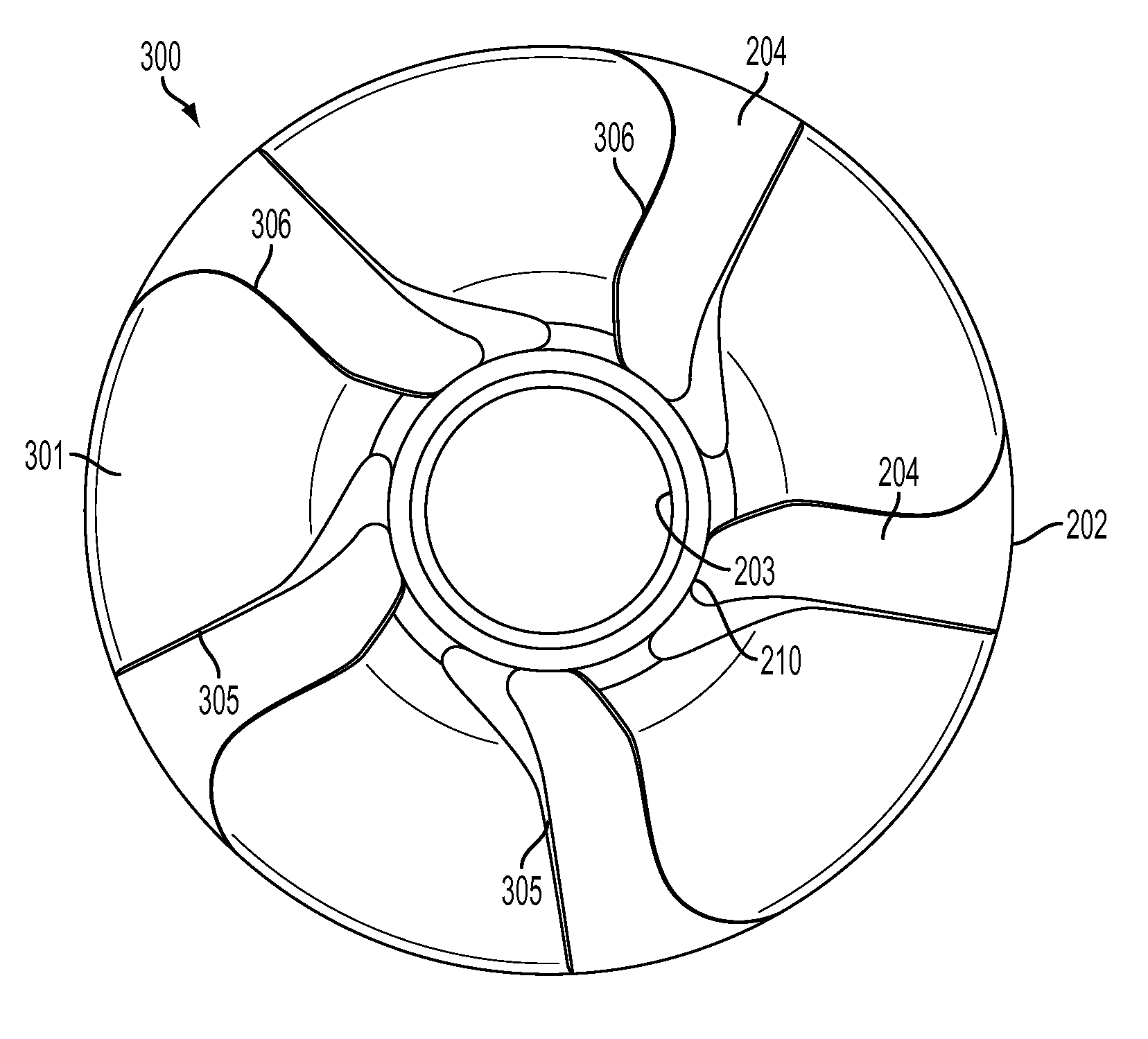
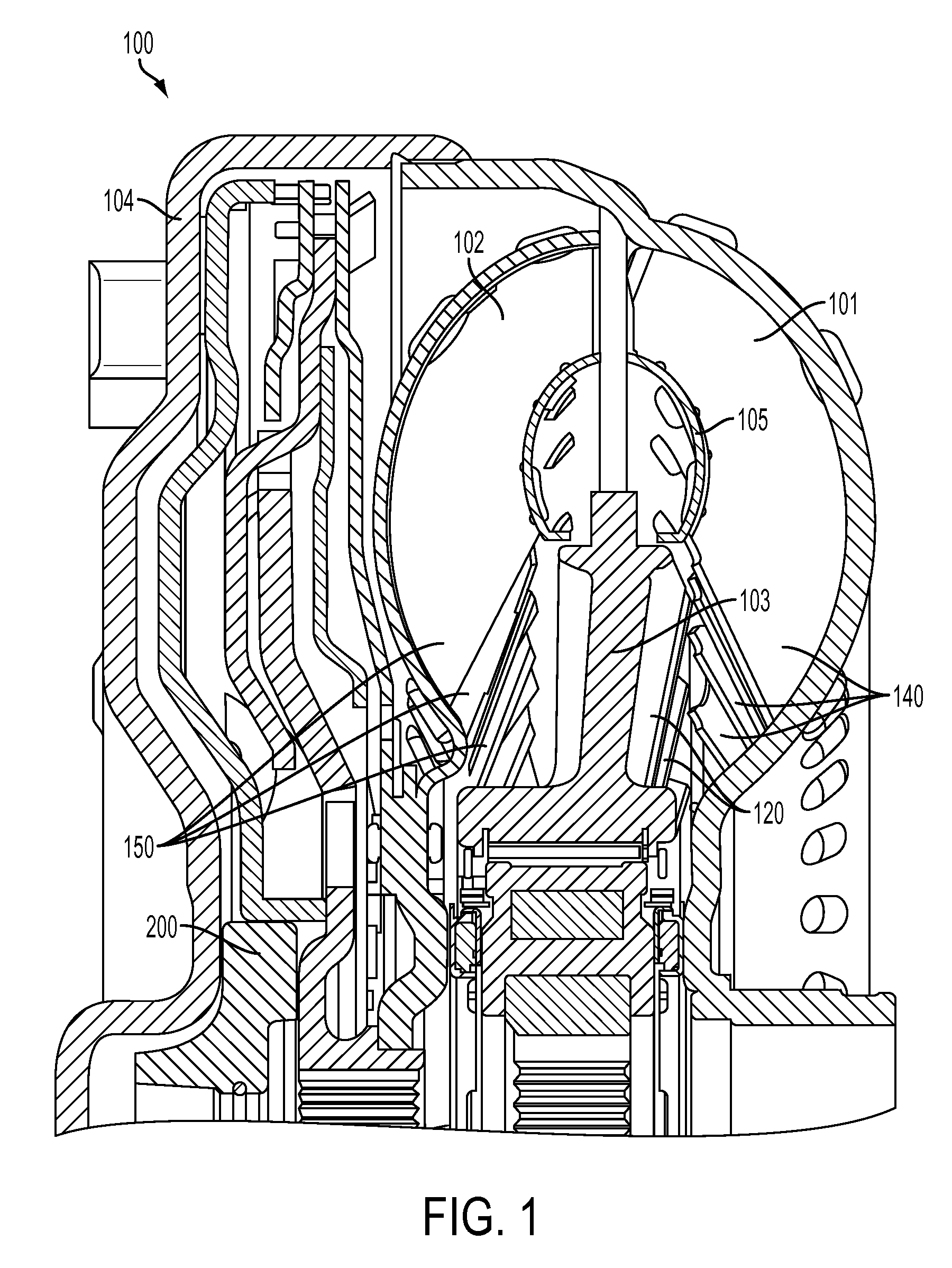
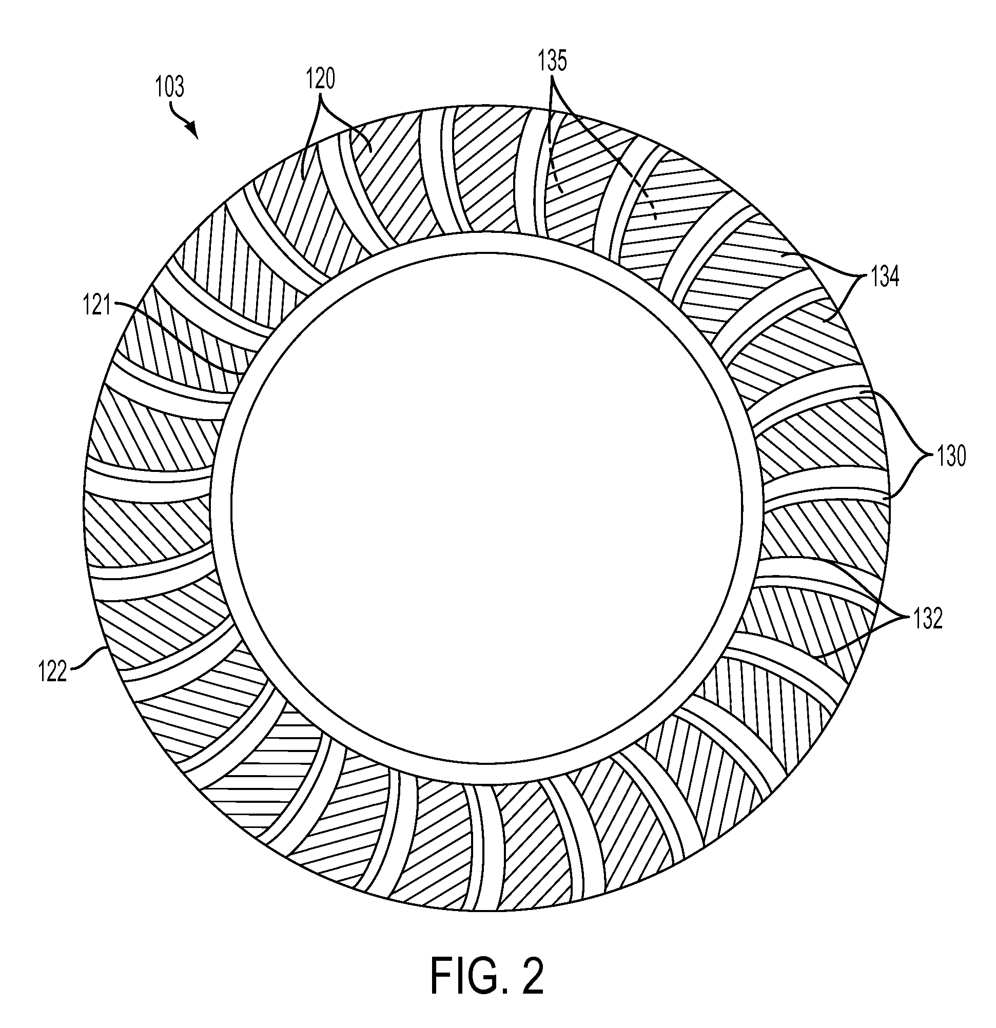
[0029]FIG. 1 is a cross sectional view of a torque converter 100 showing the location of an impeller 101, turbine 102, stator 103, cover 104, torus ring, 105, and thrust washer 200. During operation of the torque converter 100, torque generated from the engine (not shown) drives the impeller 101. The cover 104 is attached to the impeller 101, so both the cover 104 and the impeller 101 rotate at the same speed as the engine. The turbine 102 has a plurality of turbine blades 150 and the impeller 101 has a plurality of impeller blades 140 oriented so that as the impeller 101 rotates, the fluid within the impeller 101 is forced out of the impeller 101 into the turbine 102, transmitting energy to the turbine 102 and forcing it to rotate. The stator 103 has a plurality of stator blades 120 oriented to direct the fluid leaving the turbine 102 into the impeller 101 in the rotational direction of the impeller 101 rather than in a direction opposing the impeller's rotation.

[0030]FIGS. 2 and 3...


PUM


Abstract

The present disclosure relates to a torque converter, and more particularly, to a torque converter containing a stator having blades with non-linear edges and non-ruled surfaces to increase fluid flow within the torque converter and improve the performance thereof.

Description

FIELD OF THE INVENTION[0001]The present disclosure relates to a torque converter, and more particularly, to a torque converter containing a stator having non-ruled blades surfaces to reduce fluid losses and improve performance.BACKGROUND OF THE INVENTION[0002]A torque converter is a fluid-filed assembly typically used in automatic and powershift transmissions. A torque converter uses fluid to transmit energy from an input, typically an engine, to an output, typically a transmission, and consists of three main components: a turbine, an impeller, and a stator. During the operation of a torque converter, torque generated from the engine drives the impeller. A cover is attached to the impeller so both the cover and impeller rotate at the same speed as the engine. The turbine is connected to an output shaft, and the stator is connected to a non-rotating support shaft. The turbine and impeller have a plurality of blades oriented so that as the impeller rotates, the fluid within the impell...

Claims


Application Information

Patent Timeline
Patent Type & Authority Patents(United States)
IPC IPC(8): F01D9/04F16H41/26F16H45/02F16H41/28
CPCF01D9/04F16H41/26F16H2041/285F16H2045/0205
Inventor FINGERMAN, MICHAELRALEY, DARRIN C
Owner FCA US
Why Eureka
Try Eureka