Safety coupling for air hoses

a safety coupling and air hose technology, applied in the direction of couplings, valve arrangements, pipe joints, etc., can solve the problems of hose attached to the plug, dangerous whipping, high manufacturing cost, etc., and achieve the effect of preventing whipping

Inactive Publication Date: 2005-08-30
SCHNELLER RUDY A +1
View PDF11 Cites 5 Cited by
  • Summary
  • Abstract
  • Description
  • Claims
  • Application Information

AI Technical Summary

Benefits of technology

[0014]The air passages are preferably each at least half the cross-sectional area of the axial bore. The air passages are arranged equidistantly around the bore to equalize the force of exiting air and prevent whipping of the hose to which the plug is attached. In a preferred embodiment, the air passages are angled outwardly back at an angle of about 45° to straighten and tension the hose when the plug is released from the coupler.

Problems solved by technology

The section of hose attached to the plug, however, is filled with compressed air and may whip about in a dangerous manner when released.
This type of system, however, is expensive to manufacture, is heavier than a standard coupling, and, because it requires two separate operations, is cumbersome and time-consuming to use.
That approach requires a specially formed coupler and a plug which is extremely difficult to manufacture.
It also does not guarantee that the hose will not whip.

Method used


Image

  • Safety coupling for air hoses
  • Safety coupling for air hoses
  • Safety coupling for air hoses

Examples


Embodiment Construction

[0025]The following detailed description illustrates the invention by way of example and not by way of limitation. The description clearly enables one skilled, in the art to make and use the invention, describes several embodiments, adaptations, variations, alternatives, and uses of the invention, including what is presently believed to be the best mode of carrying out the invention.

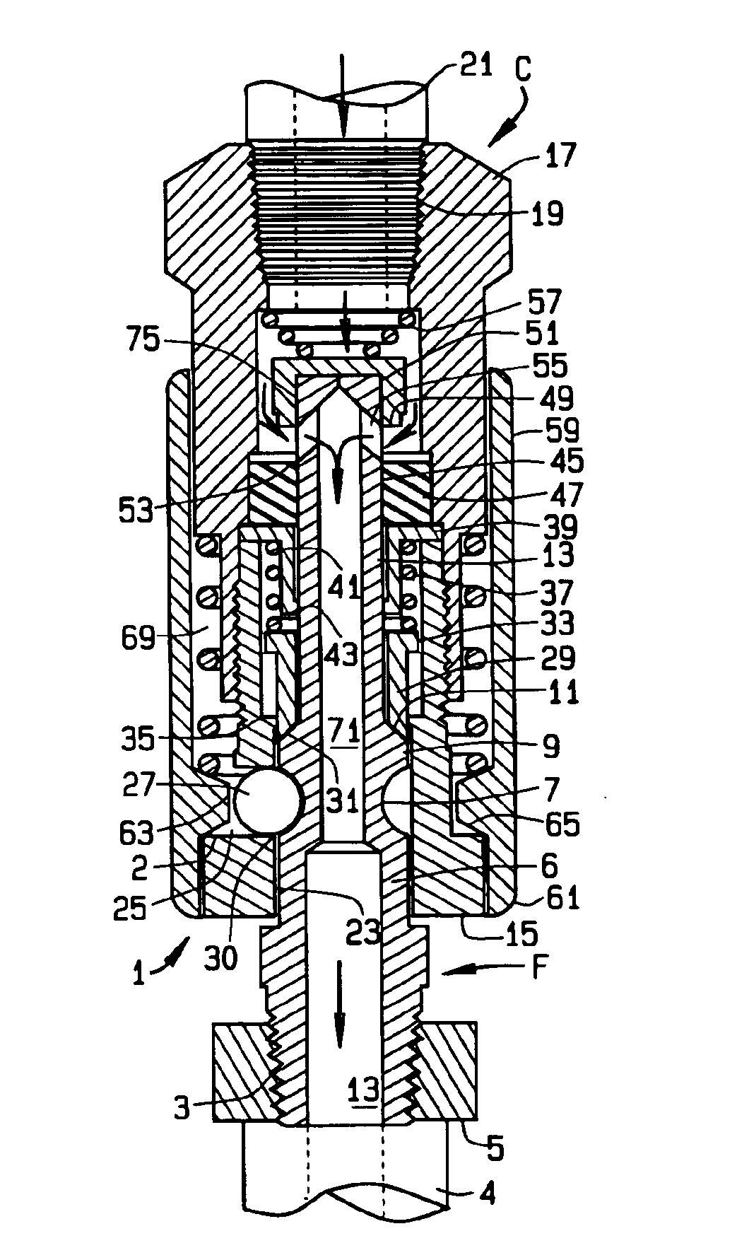
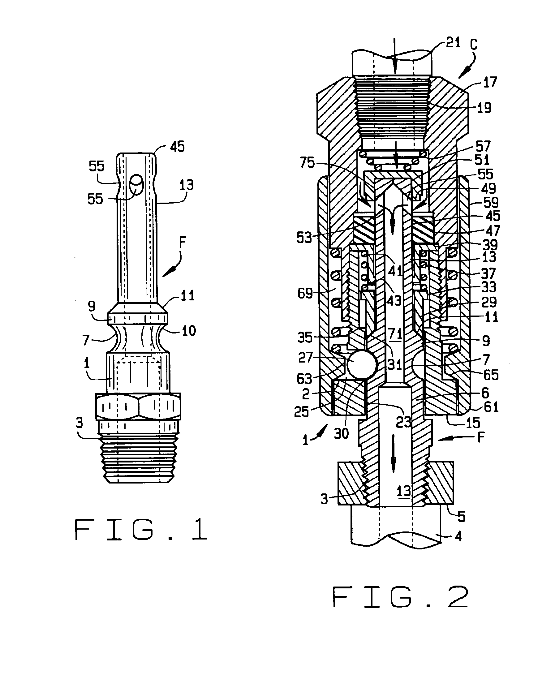
[0026]Referring now to the drawings, and in particular to FIGS. 1 and 2, one illustrative embodiment of coupling of the present invention is indicated by reference numeral 1. It will be seen that this embodiment is a modification of the coupling of the above-mentioned Schneller, U.S. Pat. No. 2,279,146. Except as mentioned below, the reference numerals refer to the same parts as in that patent.

[0027]The coupling 1 includes a plug part F and a coupler part C. The plug F includes a threaded portion 3 for fastening the plug to a length of hose 4 through a standard threaded hose fitting 5. The hose 4 is illu...


PUM


Abstract

A coupling for an air hose that reduces or eliminates whipping of the free end of the hose when the coupling is detached. The coupling comprises a one-piece plug member, the plug member comprising a fitting at a first axial end, the fitting being adapted for connection to an air hose, an external circumferential groove, a beveled external shoulder forming a wall of the groove, an axial bore, the axial bore being closed at a second axial end of the plug member, and a plurality of air passages intersecting the axial bore near the closed end of the bore; a two-piece coupler member, the coupler member receiving the plug member and releasably locking with the groove on the plug member; the coupler member comprising a ring seal trapped between the two pieces of the coupler member, and a valve member seatable on an axial side of the ring seal. The plug member, when coupled with the coupler member, extends at least partially through the ring seal, forms a seal with it, displaces the valve member, and puts the air passages in the plug member functionally on the same axial side of the ring seal as the valve member. The air passages in the plug member are preferably collectively larger in cross-section than the bore, and preferably direct air from the bore back toward the open end of the plug. The invention permits simple adaptation of existing couplings to the improved design by modifying only the plug and the valve.

Description

CROSS-REFERENCE TO RELATED APPLICATIONS[0001]This application claims priority of U.S. Provisional applications Ser. No. 60 / 433,149, filed Dec. 13, 2002, Ser. No. 60 / 433,152, filed Dec. 13, 2002, and Ser. No. 60 / 437,150, filed Dec. 30, 2002, the disclosures of which are incorporated by reference herein.STATEMENT REGARDING FEDERALLY SPONSORED RESEARCH[0002]Not Applicable.BACKGROUND OF THE INVENTION[0003]This invention relates to quick-connect couplings for hoses carrying compressed fluid. It is particularly adapted for use in hoses carrying compressed air to a tool or other equipment, although its usefulness is not limited thereto.[0004]Compressed air hoses generally include a quick-connect coupling for connecting tools and the like. The coupling includes a female portion, also known as the coupler, connected to a source of compressed air, and a male portion, also known as the plug or nipple, generally attached to the equipment. Both the male and female portions include an axial bore ...

Claims


Application Information

Patent Timeline
Patent Type & Authority Patents(United States)
IPC IPC(8): F16L37/00F16L37/23
CPCF16L37/23
Inventor SCHNELLER, RUDY A.SCHNELLER, MICHAEL A.
Owner SCHNELLER RUDY A
Why Eureka
Try Eureka