Siderail mounting assembly

a technology for supporting assemblies and bedside rails, which is applied in the directions of wheelchairs/patient conveyances, transportation and packaging, and bedsofas, can solve the problems of difficult and cumbersome operation of siderail support assemblies, and achieve the effect of facilitating the release of bedside rails

Active Publication Date: 2005-09-06
STRYKER CORP
View PDF10 Cites 55 Cited by
  • Summary
  • Abstract
  • Description
  • Claims
  • Application Information

AI Technical Summary

Problems solved by technology

However, several of the known bed siderail support assemblies are difficult and cumbersome to operate and it is not immediately intuitive how the release mechanism for the siderail is to function in order to facilitate movement of the bed siderail from a fully deployed position to a retracted and stowed position to facilitate quick access to a person lying on the patient support deck.

Method used


Image

  • Siderail mounting assembly
  • Siderail mounting assembly
  • Siderail mounting assembly

Examples


Embodiment Construction

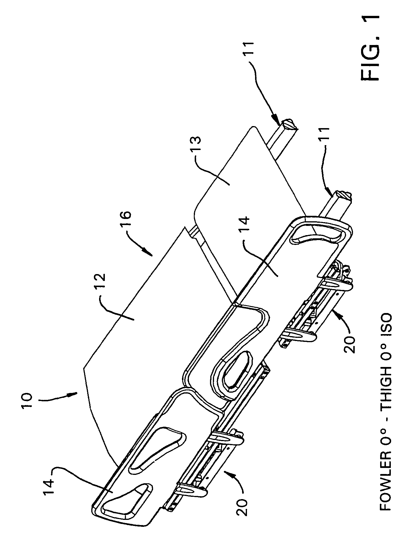
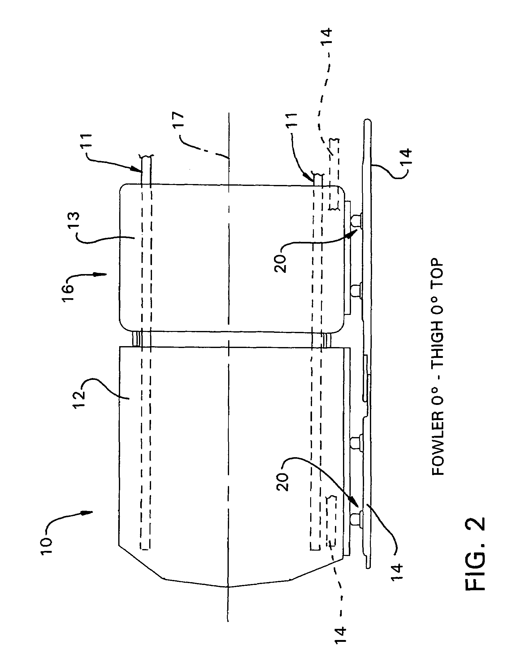
[0015]FIG. 1 is an isometric view of a bed 10 having a frame 11 and a head end section 12 and a seat and thigh section 13, hereinafter referred to as the seat section, mounted on the frame 11. A foot end section (not illustrated) is not deemed part of this invention and, accordingly, it is not shown in the drawings nor described herein. Drive mechanisms (not illustrated) are provided for effecting a relative movement between the head end section 12 and the seat section 13. The bed 10 has two pairs of bed siderails 14 provided along opposite lateral edges of the patient support deck 16 defined by the illustrated head end section 12 and seat section 13. A bed siderail support assembly 20 is provided for each siderail 14. As illustrated in FIG. 1, only one side of the bed 10 is illustrated as having the bed siderails 14 thereon. Since the bed siderail support assemblies 20 are each identical to one another, only one bed siderail support assembly will be described herein, it being under...


PUM


Abstract

A bed siderail support assembly which includes a frame, a support deck mounted on the frame and having upwardly and downwardly facing sides. The support deck has a head end, a foot end and opposite lateral edges extending between the head end and the foot end. At least one siderail is oriented along side of at least one of the lateral edges and a connecting mechanism is provided which is configured to connect the siderail to either the frame or the downwardly facing side of the support deck. The connecting mechanism includes a support configured for securement to either the frame or the support deck, an elongate toothed rack longitudinally movably mounted on the support, a pair of parallel arms pivotally mounted on the support, a toothed pinion gear on each arm supported for meshing engagement with the toothed rack and a mount pivotally secured to each of the arms and being configured to support a bed siderail thereon.

Description

FIELD OF THE INVENTION[0001]This invention relates to a bed siderail support assembly and, more particularly, to a siderail support assembly that is configured for movement from a stowed position beneath a patient support deck to a fully deployed position oriented along side of the patient support deck.BACKGROUND OF THE INVENTION[0002]Beds with siderails are known. Many of the bed siderail support assemblies facilitate movement of the siderail to and between positions wherein the siderail is stored beneath the patient support deck to a fully deployed position whereat the bed siderail is oriented along side of the patient support deck. However, several of the known bed siderail support assemblies are difficult and cumbersome to operate and it is not immediately intuitive how the release mechanism for the siderail is to function in order to facilitate movement of the bed siderail from a fully deployed position to a retracted and stowed position to facilitate quick access to a person l...

Claims


Application Information

Patent Timeline
Patent Type & Authority Patents(United States)
IPC IPC(8): A47C21/00A47C21/08A61G7/05A61G5/10
CPCA61G5/10A61G7/0507A61G2007/052A61G2007/0514A61G7/0514A61G7/052
Inventor MORIN, MARCO
Owner STRYKER CORP
Why Eureka
Try Eureka