Vehicle seat

a technology for vehicles and seats, applied in the field of vehicles seats, can solve problems such as increasing the risk of driver injuries

Inactive Publication Date: 2005-09-06
AUTOLIV DEV AB
View PDF41 Cites 118 Cited by
  • Summary
  • Abstract
  • Description
  • Claims
  • Application Information

AI Technical Summary

Benefits of technology

[0016]Preferably means are provided to permit rearward movemen...

Problems solved by technology

If, however, the head of the driver is close to the headrest when the rear impact occurs, the headrest will impart a substantial forward acceleration...

Method used


Image

  • Vehicle seat
  • Vehicle seat
  • Vehicle seat

Examples


Embodiment Construction

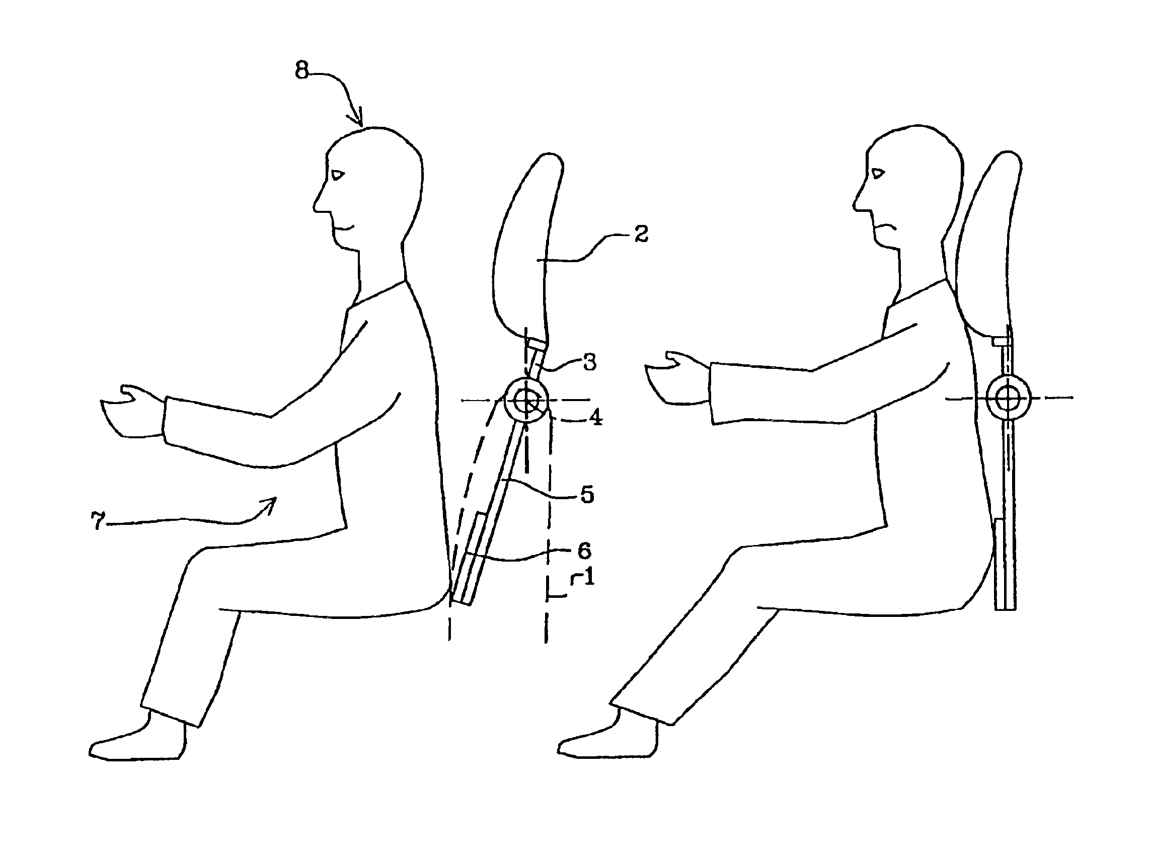
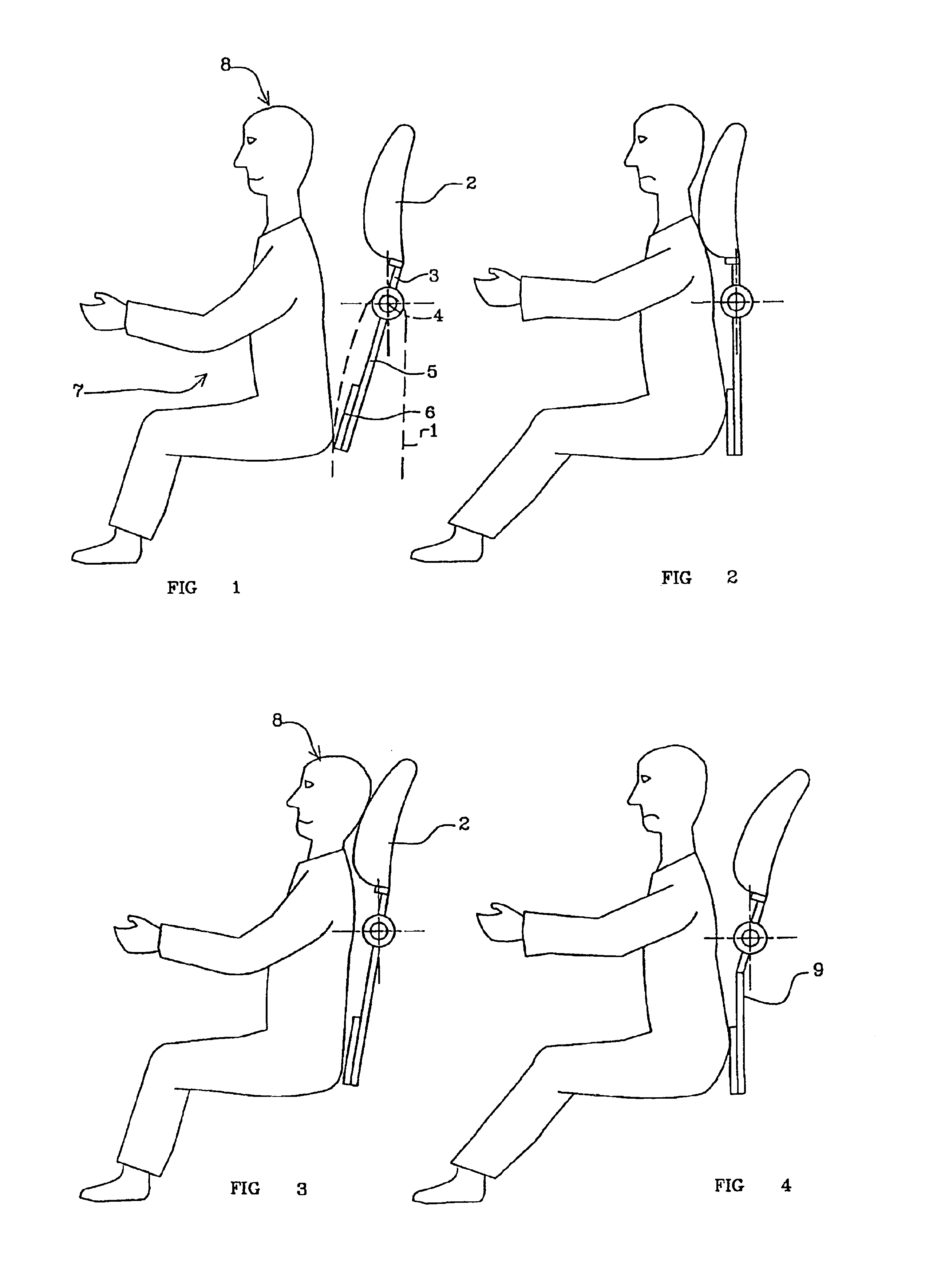
[0028]Referring initially to FIG. 1 a vehicle seat has a backrest 1, which is shown in phantom in FIG. 1 but which is omitted from the remaining drawings. Mounted on the backrest 1 is a headrest 2. The headrest is supported by the upper part of one or two generally upright support rods 3. (Only one rod is shown in the drawings.) The or each support rod is pivotally connected, by a pivotal connection 4, to the frame member provided in the backrest 1. The connection 4 may include a biasing spring which biases the headrest with a clockwise rotation (as seen in FIG. 1) to the position shown in FIG. 1.

[0029]The support rod includes a lower part 5 that extends below the pivotal connection 4 within the backrest of the seat, where it is connected to a pressure plate 6 that is adapted to move rearwardly, within the seat back, when the torso of an occupant 7 of the seat moves rearwardly, relative to the back of the seat in a rear impact situation.

[0030]As shown in FIG. 1 the occupant 7 has an...


PUM


Abstract

A vehicle seat has a back-rest (1) carrying a head-rest (2). A mechanism is provided to move the head-rest (2) forwardly relative to the back-rest (1) in response to a rear impact situation. An element (9) is operatively located between the head-rest (2) and the mechanism (6) which is adapted to yield when exposed to a force in excess of a predetermined force. Thus the force that can be applied by the head-rest (2) to a head (8) of an occupant of the seat, is limited to be a maximum of 200 Newtons, with the preferred value being 100 Newtons.

Description

BACKGROUND OF THE INVENTION[0001]1. Field of the Invention[0002]THE PRESENT INVENTION relates to a vehicle seat.[0003]2. Description of Related Art[0004]It has been proposed in U.S. Pat. No. 5,378,043 to provide a vehicle seat with a headrest that moves forwardly in the event that a rear impact should occur to minimise the risk of whiplash injuries occurring. The headrest is mounted on upright support bars that are pivotally connected to the upper part of the frame of the backrest of the seat, and which are also connected to a pressure plate which is within the backrest of the seat. In a rear impact situation, when the driver is in a typical position with his head spaced in front of the headrest, initially the torso of the driver will move rearwardly pressing his torso into the backrest of the seat and the pressure plate will thus move rearwardly causing the headrest to move forwardly to ‘catch’ the head of the driver. The head and torso will then be accelerated at the same rate, th...

Claims


Application Information

Patent Timeline
IPC IPC(8): B60N2/48
CPCB60N2/4838B60N2/4885B60N2/838B60N2/888
Inventor H.ANG.LAND, YNGVESVANTESSON, ANDERS
Owner AUTOLIV DEV AB
Why Eureka
Try Eureka