Shutter assembly for a luminaire

a technology for luminaires and shutter blades, which is applied in the field of shutter assembly, can solve the problems of high material and assembly labor costs, large size and poor reliability, and is difficult to locate all shutter blades at or very close to the desired optical point, etc., and achieves the effects of simple, reliable and compa

Inactive Publication Date: 2005-09-06
ELECTRONIC THEATRE CONTROLS
View PDF14 Cites 14 Cited by
  • Summary
  • Abstract
  • Description
  • Claims
  • Application Information

AI Technical Summary

Benefits of technology

[0006]A primary object of the present invention is to provide an improved shutter assembly for a luminaire. More specific objects of the invention are to provide a framing shutter assembly that is very simple, easy and inexpensive to fabricate and assemble, reliable, and compact, thereby overcoming disadvantages of known shutter assemblies and fulfilling the long standing need for a simple, reliable and compact framing shutter assembly for a luminaire.

Problems solved by technology

Typically, known arrangements are very complex, requiring many intricate parts and assembly operations and resulting in high material and assembly labor costs, large size and poor reliability.
Large size is a problem because it may require a large luminaire housing to contain the shutter assembly and because it may make it difficult to locate all of the shutter blades at or very close to the desired optical point such as at a focus point along the light path.
In many designs the motors used for operating the shutters have been mounted for movement in the assembly and have been drivingly connected to the shutters by complicated and expensive mechanisms.
A disadvantage of movably mounted motors is the need to route electrical cabling to the moving motors.

Method used


Image

  • Shutter assembly for a luminaire
  • Shutter assembly for a luminaire
  • Shutter assembly for a luminaire

Examples


Embodiment Construction

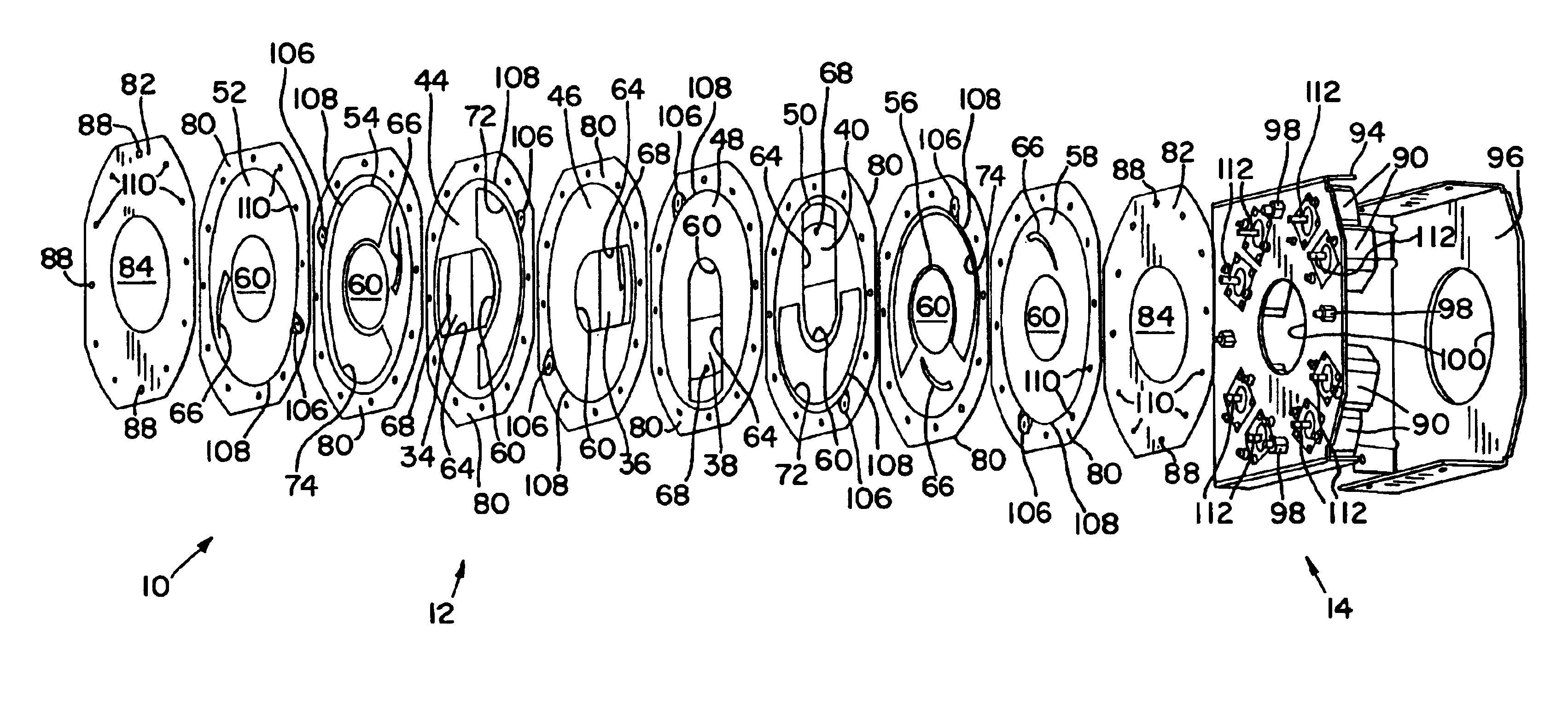
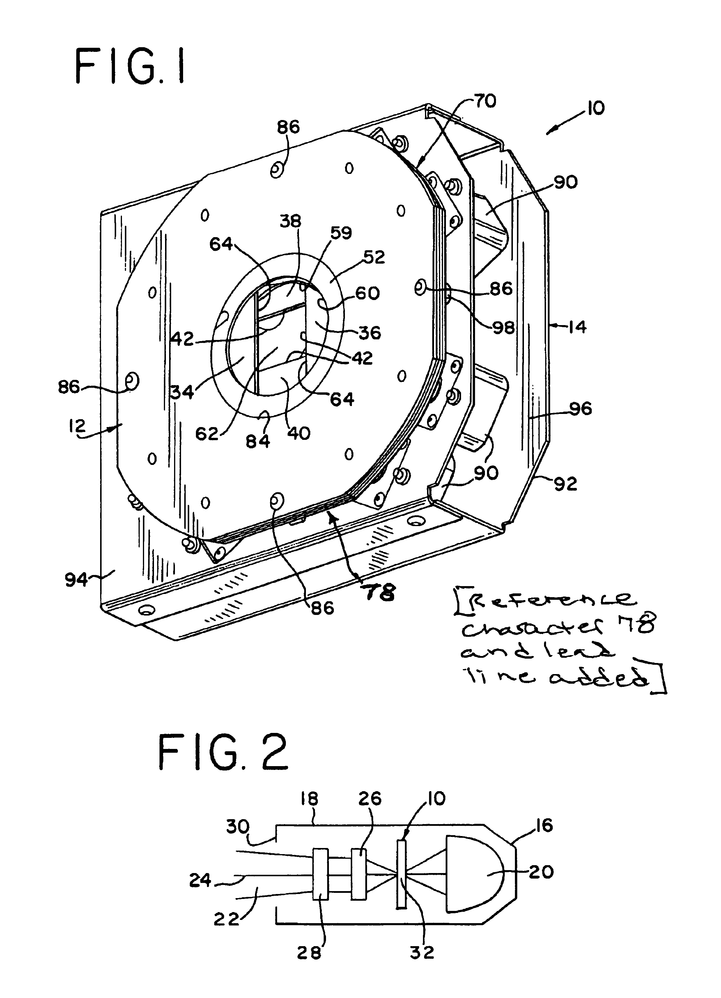
[0016]Having reference now to the drawing, a framing shutter assembly generally designated as 10 is seen in FIG. 1. The shutter assembly 10 is constructed in accordance with the principles of the present invention and includes a shutter section 12 and a drive motor section 14. In accordance with a feature of the invention, the components of the shutter section are made from sheet metal to provide a compact and inexpensive construction that is easily fabricated and assembled, and is sturdy, simple and reliable.

[0017]FIG. 2 is a simplified diagrammatic view of a theatrical luminaire 16 provided with the shutter assembly 10 of the present invention. A luminaire housing 18 contains a light source including a reflector 20. A beam 22 of light is emitted from the reflector 20 and travels in the direction of its longitudinal axis 24 through a lens system including rear and front optical lenses 26 and 28. The light beam 22 is projected through a light exit opening 30 in the housing 18. The s...


PUM


Abstract

A shutter section includes a stack of circular plates independently rotatable in a nest formed as a laminar formation of rings. The plates have central openings defining a light path. Four central plates in the stack are shutter guide plates with radial guide slots slideably holding shutter blades. Two outer pairs of plates are shutter drive plates connected by cams to the shutter blades. Simultaneous rotation of a shutter guide plate and associated shutter drive plate causes rotation of an associated shutter blade around the light path. Rotation of a shutter drive plate while the associated shutter guide plate is stationary causes the cam to move the associated shutter blade radially. The nest is enclosed by end plates. A motor section has motors driving pinions to rotate the circular plates. The circular plates, rings pinions and shutter blades are made of sheet metal.

Description

FIELD OF THE INVENTION[0001]The present invention relates to a shutter assembly, and more particularly to an improved framing shutter assembly for a luminaire.DESCRIPTION OF THE PRIOR ART[0002]Theatrical luminaires can be provided with shutters to provide a projected, framed light beam of a selected shape and size. In typical arrangements, four shutter blades are mounted within the luminaire housing for movement relative to the light path. The blades can be translated radially into and out of the light path and each can be rotated in the peripheral direction around of the light beam. By arranging the shutter blades, the projected light beam can be square or rectangular or have other straight sided shapes such as triangular or trapezoidal, and the projected shape can be oriented at a selected rotational position.[0003]In the past, manually operated shutters were common. In a manually operated shutter assembly, handles projecting from the sides of the luminaire are manipulated to plac...

Claims


Application Information

Patent Timeline
Patent Type & Authority Patents(United States)
IPC IPC(8): F21V11/08F21V11/00F21V11/18F21S8/00
CPCF21V11/08F21V11/18F21W2131/406
Inventor GENNRICH, DAVID JAMESROBERTS, SHELDON
Owner ELECTRONIC THEATRE CONTROLS
Why Eureka
Try Eureka