EMI foil laminate gasket

a technology of emi foil and laminate, which is applied in the direction of sealing, conductive pattern formation, electrical apparatus casings/cabinets/drawers, etc., can solve the problems of reducing and affecting the efficiency of ground conduction paths

Inactive Publication Date: 2005-09-13
SCHLEGEL SYST
View PDF36 Cites 56 Cited by
  • Summary
  • Abstract
  • Description
  • Claims
  • Application Information

AI Technical Summary

Benefits of technology

[0019]In the present invention, conductive sheath issues of both flexibility and the thickness-of-metal are addressed by providing a sheath having a laminated structure. The laminate includes a substrate composed of a woven or non-woven fabric, or polymeric film and preferably a nonporous film. Laminated to this substrate is a copper or aluminum foil. The substrate may range in thickness from 0.25 to 8 mils whereas the foil generally has a thickness of about 0.2 mils or 10 times the thickness of a metal layer produced by electroless or vapor deposition.

Problems solved by technology

Gaps also interfere with electrical currents running along the surfaces of the cabinets from EMI energy, which is absorbed and is being conducted to ground.
The gaps reduce the efficiency of the ground conduction path and may even result in the shield becoming a secondary source of EMI leakage from gaps acting as slot antennae.
A disadvantage of such materials is that they are costly to manufacture and there are practical limits to the thickness of a metal layer that can be deposited either by vapor deposition or by electroless plating.
Another drawback of fabrics coated with metal by electroless or vapor deposition is that they tend to be porous.
However metal foils per se are not compressible and therefore a metal foil gasket is not generally used between mating parts.
Nor are metal foils generally used for wrapping around a compressible core because a foil is relatively stiffer than a metallized fabric or film and may crack if sharply bent.
Consequently, the foil is subject to cracking or wrinkling when a gasket made with foil is repeatedly compressed and decompressed.
In addition, most foils will corrode and are not galvanically compatible with other metals so that the use of foils, as a gasket sheathing material, is limited.

Method used


Image

  • EMI foil laminate gasket
  • EMI foil laminate gasket
  • EMI foil laminate gasket

Examples


Embodiment Construction

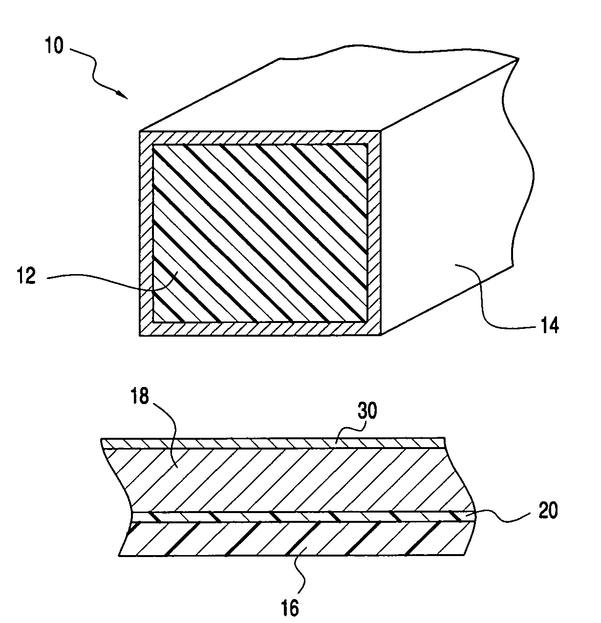
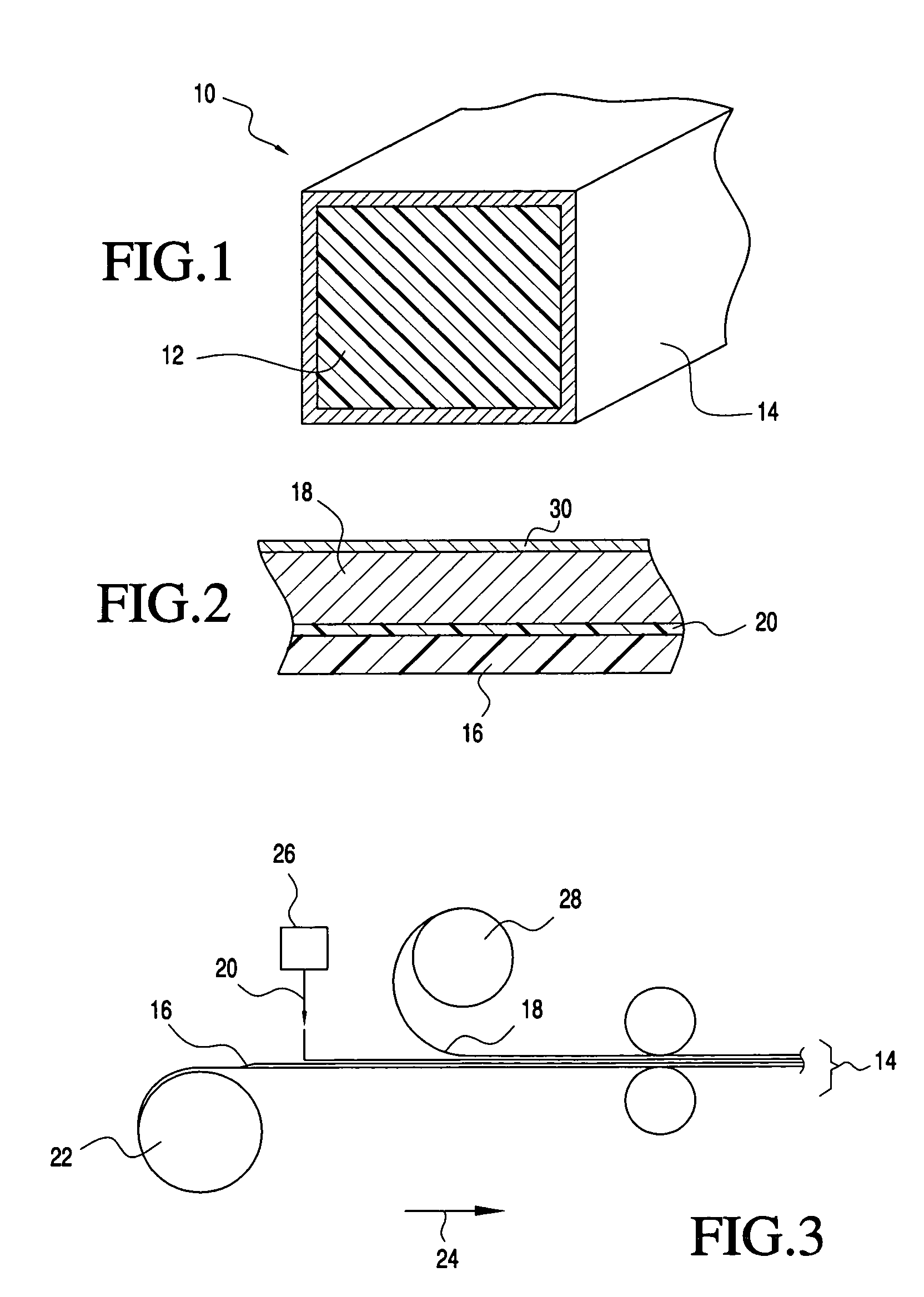
[0034]Referring to the drawings, FIG. 1 shows a conductive gasket of the present invention generally indicated at 10. The gasket comprises a foam core 12 which is resilient and compliant over a range of temperatures and which preferably exhibits good compression set characteristics such that the material will “spring back” after repeated compression and decompression and even after long periods of compression. For example, a suitable material for the core 12 is an open-celled polyether polyurethane foam in a high-resiliency formula. In a preferred embodiment the compressive set of the foam is 1% at ambient temperature and less than 5% at 70° C. (158° F. when compresses 50% for 22 hours.

[0035]Surrounding the core 12 is a conductive sheath 14. It should be appreciated that the shape of the cross section of the gasket as shown is for purposes of illustration only. Also, the thicknesses of the various components are not to scale but are shown greatly enlarged for clarity. For example th...


PUM

PropertyMeasurementUnit
thickaaaaaaaaaa
frequenciesaaaaaaaaaa
surface resistivityaaaaaaaaaa

Abstract

A conductive electromagnetic interference (EMI) shielding gasket having a compressible non-conductive core enwrapped with a conductive sheath. The sheath is a laminate formed by laminating a conductive metal foil at least 0.2 mils thick to a flexible non-conductive substrate, preferably a non porous polyester film.

Description

CROSS-REFERENCE TO RELATED APPLICATIONS[0001]NoneSTATEMENT REGARDING FEDERALLY SPONSORED RESEARCH OR DEVELOPMENT[0002]Not appliableREFERENCE TO A “SEQUENCE LISTING”[0003]Not applicable.BACKGROUND OF THE INVENTION[0004]1. Field of the Invention[0005]The present invention relates to a conductive gasket as may be used in applications requiring electromagnetic interference (EMI) shielding. More particularly, the present invention relates to an EMI gasket that has a relatively thick metal conductive layer and a flexibility that resists cracking when bent.[0006]2. Description of Related Art[0007]Many modern electronic devices emit or are sensitive to electromagnetic interference (EMI) at high frequencies. Electromagnetic interference is understood to mean undesired conducted or radiated electrical disturbances from an electric or electronic apparatus, including transients, which can interfere with the operation of other electrical or electronic apparatus. Such disturbances can occur anywh...

Claims


Application Information

Patent Timeline
Patent Type & Authority Patents(United States)
IPC IPC(8): H05K9/00H05K5/00
CPCH05K9/0015H05K9/0084Y10T29/49155Y10S277/92
Inventor MISKA, STANLEY R.
Owner SCHLEGEL SYST
Why Eureka
Try Eureka