Low cost safety switch interlock defeat operator

a safety switch and operator technology, applied in the direction of electrical apparatus, shutters/guards preventing contact access, substation/switching arrangement details, etc., can solve the problem of adding difficulty to the servicing of equipment therein

Active Publication Date: 2005-09-13
EATON INTELLIGENT POWER LIMITED
View PDF3 Cites 17 Cited by
  • Summary
  • Abstract
  • Description
  • Claims
  • Application Information

AI Technical Summary

Benefits of technology

[0007]The present invention provides an apparatus for defeating an interlock for an electrical cabinet. The interlock permits a technician qualified to do so to open the cabinet while current if fl

Problems solved by technology

However, such interlocks also add difficu

Method used


Image

  • Low cost safety switch interlock defeat operator
  • Low cost safety switch interlock defeat operator
  • Low cost safety switch interlock defeat operator

Examples


Embodiment Construction

[0019]The present invention provides a defeat mechanism for an interlock, permitting qualified personnel to open an electrical cabinet secured by the interlock when current is flowing through the electrical equipment therein.

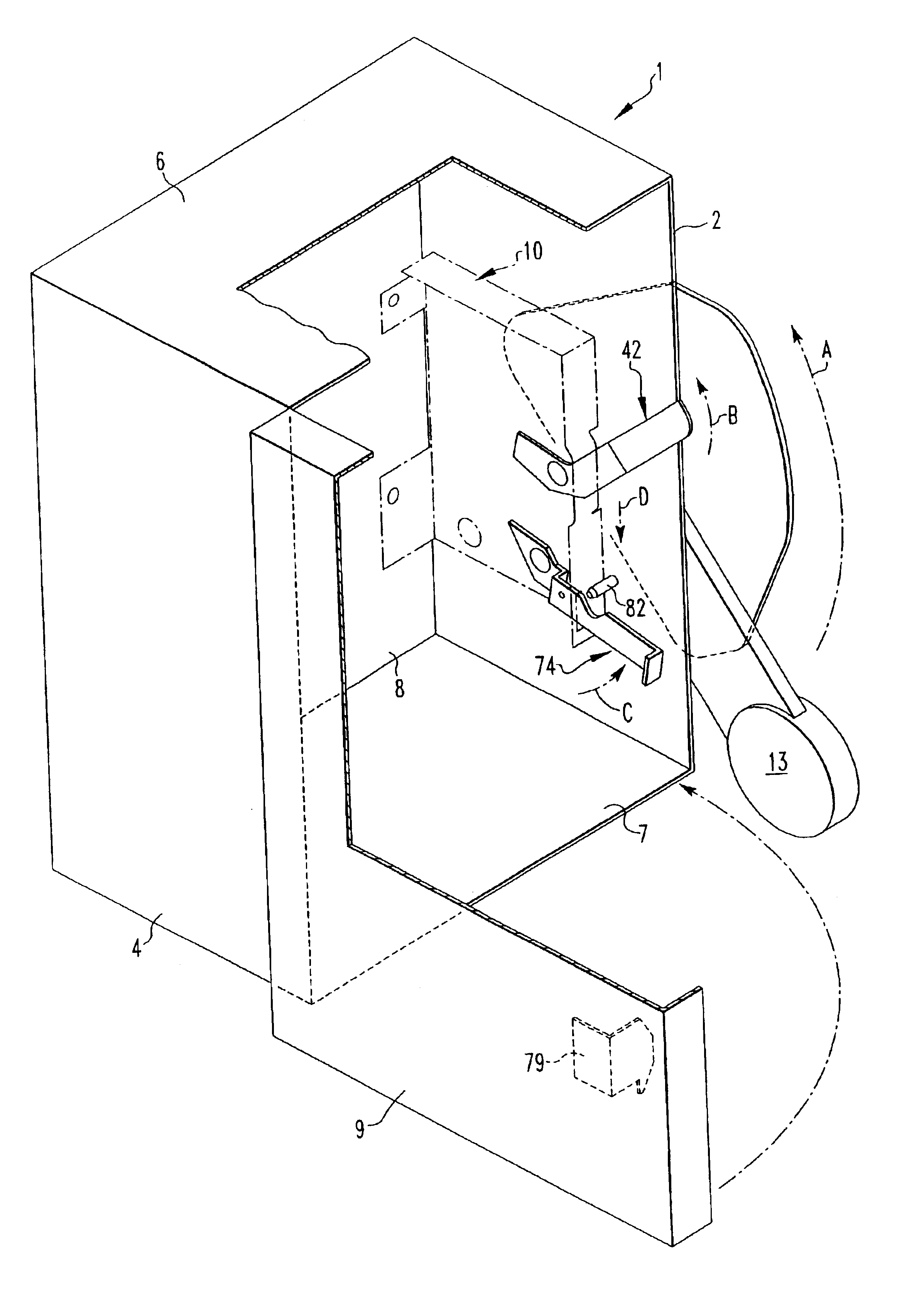
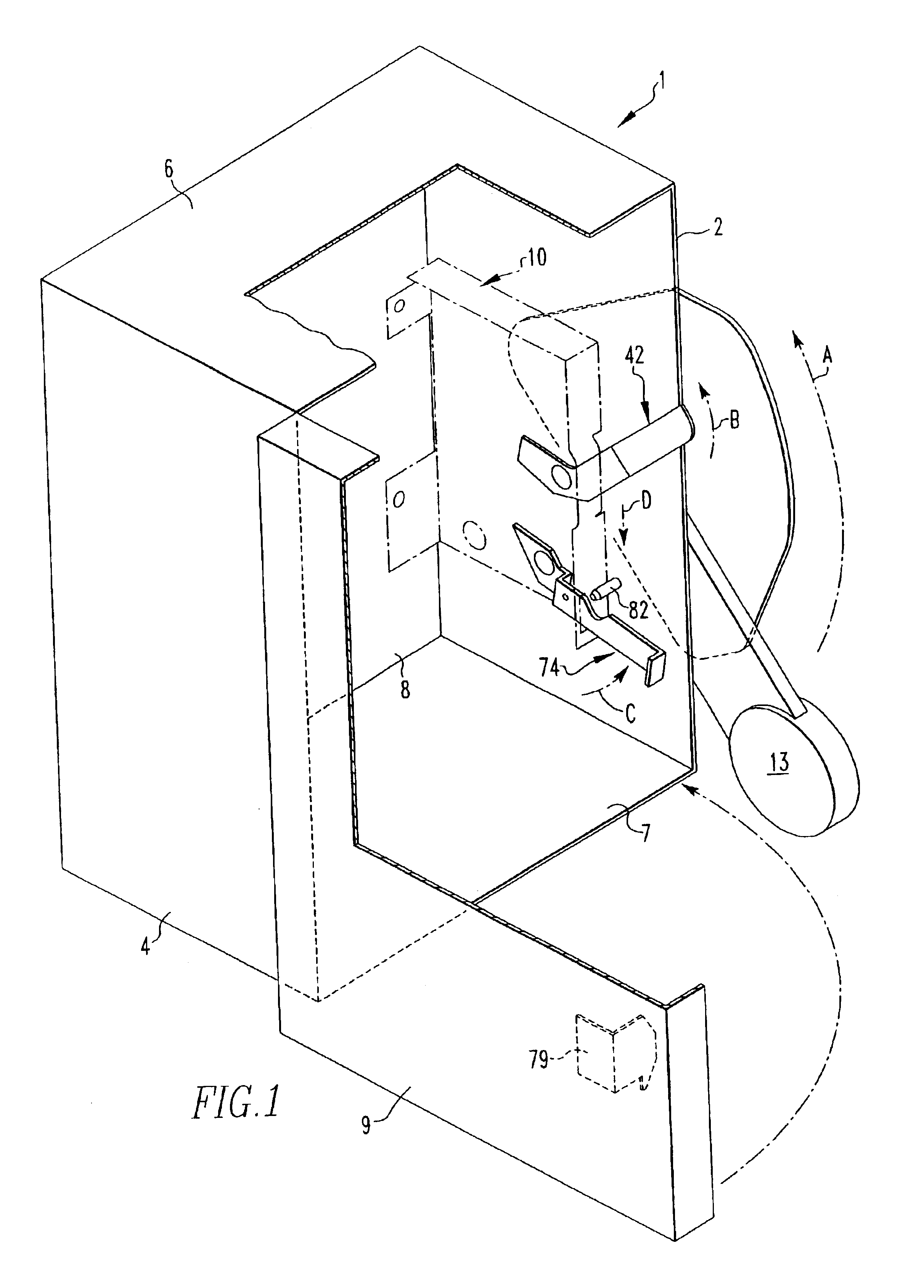
[0020]A cabinet 1, shown in FIG. 1, with which the interlock defeat will be used will include a pair of sides 2, 4, a top 6, a bottom 7, a back 8, and a hingedly secured door 9. Typically, if the door is hingedly secured to the second of the two sides, the interlock holding the door closed will be secured to the first of the two sides.

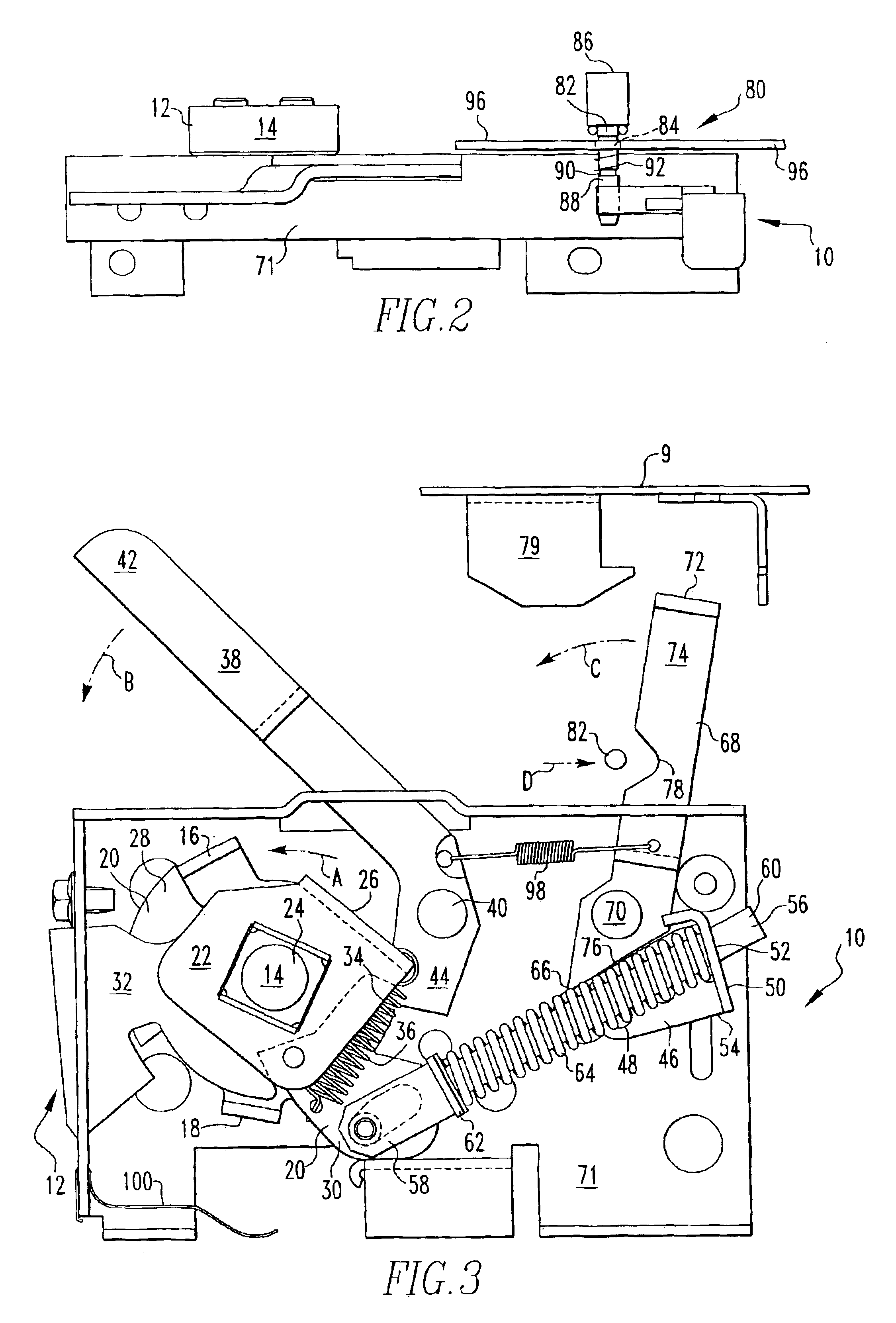
[0021]Referring to FIGS. 2-3, an interlock mechanism 10 with which the present invention will be used is illustrated. The interlock mechanism 10 is best understood through an explanation of the working of the power switch assembly 12. The power switch assembly 12 includes an operating handle 13 secured to a mechanism drive hub 14. The operating handle 13 is illustrated in FIG. 1 in the off position, and moves in the direction of ar...


PUM


Abstract

An apparatus for defeating an interlock for an electrical cabinet permits a technician qualified to service the equipment within the cabinet to defeat the interlock and open the cabinet while current is flowing through the equipment therein, while permitting the interlock to continue to resist unauthorized access to the interior of the cabinet.

Description

BACKGROUND OF THE INVENTION[0001]1. Field of the Invention[0002]The present invention relates to interlocks for electrical cabinets. More specifically, the present invention provides an apparatus for defeating an interlock, thereby permitting a technician to open the cabinet when the circuit therein is closed, and thereby facilitating servicing of the equipment therein.[0003]2. Description of the Related Art[0004]Various interlocks are commonly used on cabinets containing electric equipment, to prevent opening of the cabinet when there is current flowing through the equipment. Such interlocks thereby protect personnel working around the equipment from unnecessary risk of injury. However, such interlocks also add difficulty to servicing of the equipment therein. It is sometimes necessary for a technician servicing the equipment to open the cabinet at a time when current is flowing through the equipment therein in order to maintain or repair the equipment.[0005]A presently used interl...

Claims


Application Information

Patent Timeline
IPC IPC(8): H02B11/00H02B11/133
CPCH02B11/133
Inventor GRAY, BUELL E.PROHASKA, RICHARD D.
Owner EATON INTELLIGENT POWER LIMITED
Why Eureka
Try Eureka