Mechanism for fastening an electronic device in computer by snapping

a technology of electronic devices and computer cases, which is applied in the direction of portable computer details, electric apparatus casings/cabinets/drawers, instruments, etc., can solve the problems of affecting the operation of the computer, so as to reduce the manufacturing cost, increase the production of the computer, and fasten or unfasten the electronic device quick and simple

Inactive Publication Date: 2005-09-13
FIRST INTERNATIONAL COMPUTER
View PDF11 Cites 29 Cited by
  • Summary
  • Abstract
  • Description
  • Claims
  • Application Information

AI Technical Summary

Benefits of technology

[0008]One object of the present invention is to provide a simple and modular snapping mechanism in a computer case for greatly increasing computer production and thus reducing the manufacturing cost. The snapping mechanism is mounted in a compartment of the case. When a user mounts an electronic device in the compartment, a second protrusion of the electronic device pushes a second hook of a pivotal member for expanding an elastic member of the snapping mechanism. Next, a post moves from the other end of a trough to the other end at the bent portion thereof along a groove. At this time, the pivotal member will pivot similar to a lever enabling a first hook of the pivotal member to urge against a first protrusion of the electronic device with the elastic member compressed. This generates a strong snapping force to fasten the electronic device. The present invention not only makes the fastening or unfastening of the electronic device quick and simple but also substantially eliminates the prior drawback which involves a tedious, time consuming process in mounting the electronic device in the compartment or removing it from the compartment.

Problems solved by technology

These drawbacks are that installation of an electronic device in a computer case or removal the same from the computer case is a tedious and inconvenient process since the interior space of the case in a mini PC is narrow and the threaded fastening of the electronic devices in frames of the computer case takes a lot of time.
Otherwise, it is susceptible of damaging other electronic devices.

Method used


Image

  • Mechanism for fastening an electronic device in computer by snapping
  • Mechanism for fastening an electronic device in computer by snapping
  • Mechanism for fastening an electronic device in computer by snapping

Examples


Embodiment Construction

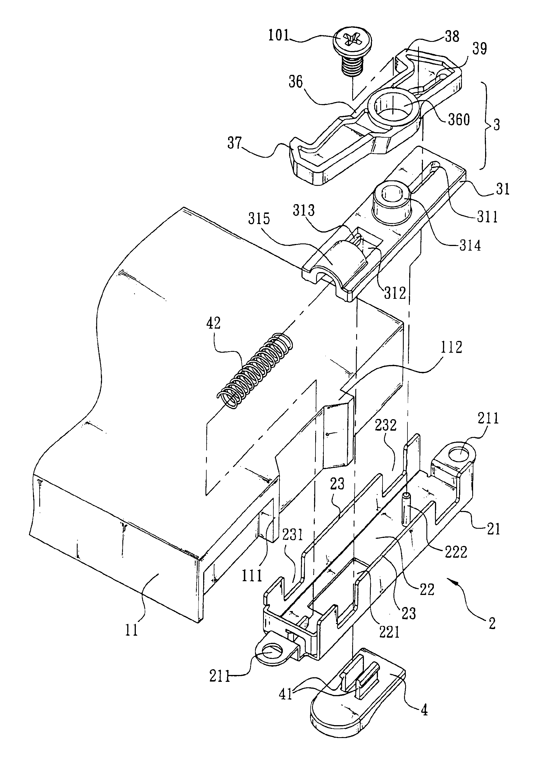
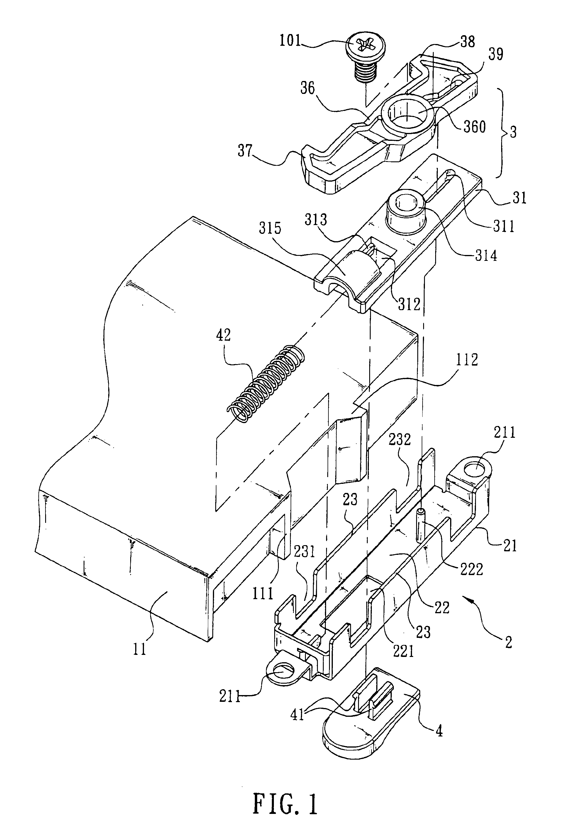
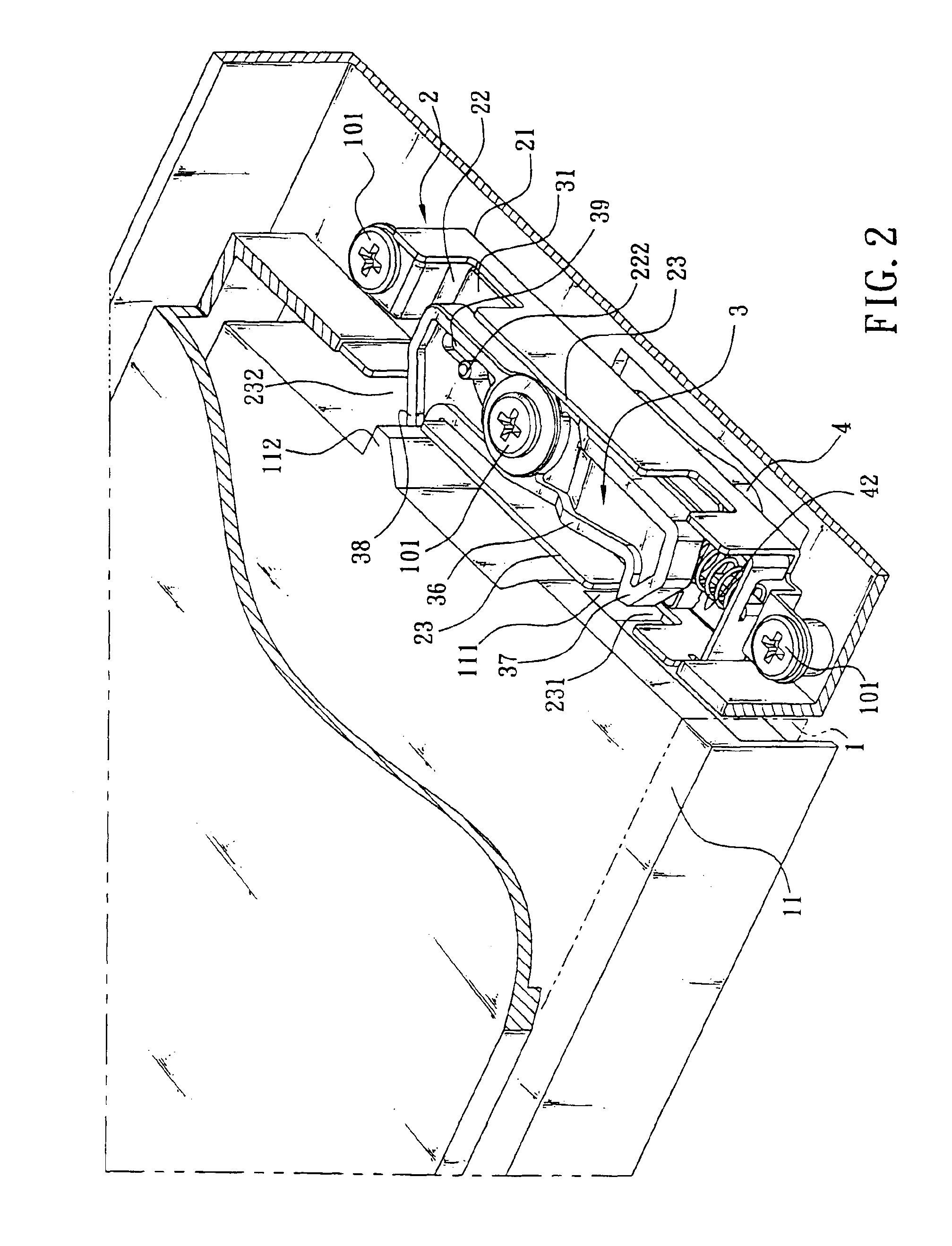
[0014]Referring to FIGS. 1, 2, 3 and 4, there is shown a mechanism for fastening (or unfastening) an electronic device in the case of a computer (e.g., mini PC) by snapping in accordance with a preferred embodiment of the invention. The snapping mechanism 2 is mounted in a compartment 1 in the case (see FIG. 2). In detail, the mechanism 2 is mounted in a side of the compartment 1. An electronic device 11 (e.g., CD, hard disk drive, battery, etc.) is fitted in the compartment 1. Spaced first protrusion 111 and second protrusion 112 are formed on a side wall of the electronic device 11. The first and the second protrusions 111, 112 are disposed corresponding to the mechanism 2.

[0015]In the embodiment, the mechanism 2 comprises an elongate seat 21 including a bottom 22 and two vertical side plates 23 to cause the seat 21 to have a section of U (see FIG. 1). An opening 211 is formed at either end of the seat 21. Two screws 101 can be driven through the openings 211 to fasten the seat 21...


PUM


Abstract

The present invention is to provide a snapping mechanism mounted in a compartment of a case of a PC comprising a second hook of a pivotal member installed within the compartment for being pushed by a second protrusion of an electronic device, while mounting the electronic device into the compartment, the pivotal member moves along a trough provided thereon from one position to another position and enables an elastic member of the snapping mechanism to pivot the pivotal member like a lever to urge a first hook thereof against a first protrusion of the electronic device with the elastic member compressed and generate a strong snapping force to fasten the electronic device within the compartment.

Description

FIELD OF THE INVENTION[0001]The present invention relates to fastening mechanisms and more particularly to a mechanism for quickly fastening or unfastening an electronic device in a computer case by snapping.BACKGROUND OF THE INVENTION[0002]Currently, there are many kinds of mini personal computers (PCs) commercially available. The mini PC has advantages of being compact and as powerful as a conventional desktop computer. Thus, more and more people like to buy mini PCs. In general, a mini PC comprises a plurality of electronic devices such as a CD, a hard disk drive, a battery, etc.[0003]It is very important to suitably customize narrow space inside the mini PC since the above electronic devices are mounted therein. Also, both assembly lines in the computer manufacturing factory and future component replacement and maintenance will be greatly beneficially or adversely affected by the well or poor arrangement of the electronic devices in the computer case. Typically, a plurality of s...

Claims


Application Information

Patent Timeline
Patent Type & Authority Patents(United States)
IPC IPC(8): E05C19/00E05C1/00E05C1/12E05C19/10G06F1/18G06F1/16
CPCE05C1/12E05C19/10G06F1/1613G06F1/1658G06F1/184G06F1/187Y10T292/0921Y10T292/0969
Inventor CHEN, CHANG-SHENGLI, CHUN-NAN
Owner FIRST INTERNATIONAL COMPUTER
Why Eureka
Try Eureka