
Portable terminal device

Inactive Publication Date: 2005-09-13
PANASONIC CORP
View PDF9 Cites 6 Cited by
  • Summary
  • Abstract
  • Description
  • Claims
  • Application Information

AI Technical Summary

Benefits of technology

[0007]In order to solve the above-mentioned conventional problems, an object of the invention is to provide a portable terminal device capable of improving the assembly property of the device without the risk of deteriorating the rigidity while achieving a thinner shape of the device main body.
[0008]A first aspect of the invention is a portable terminal device with an antenna main body to be stored in an antenna tube in a housing in the case an antenna is contracted, wherein a gutter-like antenna tube storage part is provided in a battery storage part in a rear case of the housing so as to store the antenna main body in the antenna tube provided in the antenna tube storage part. According to the configuration, the section modulus of the rear case of the housing in terms of the strength of materials can be large, and thus deterioration of the rigidity can be prevented even in the case the device main body is made thinner.
[0009]A second aspect of the invention is the portable terminal device according to the first aspect, wherein a rib is provided along the antenna storage direction in the antenna tube storage part. According to the configuration, the section modulus of the rear case of the housing in terms of the strength of materials can further be large, and thus deterioration of the rigidity can be prevented even in the case the device main body is made thinner.
[0010]A third aspect of the invention is the portable terminal device according to the first or second aspect, wherein a protrusion part of the gutter-like antenna tube storage part is formed on the battery side in the battery storage part so as to store the antenna tube in a recess part of the antenna tube storage part formed on the opposite side with respect to the battery side. According to the configuration, since the operation of inserting the antenna tube through the hole provided in the housing can be eliminated at the time of assembly, the assembly property of the device can be improved. Moreover, since the hole for inserting through the antenna tube provided commonly in the conventional housing is eliminated, entrance of sweat or water from the battery storage part into the housing inside through the hole can be avoided so as to prevent adverse effects on the electronic parts.
[0011]A fourth aspect of the invention is the portable terminal device according to the third aspect, wherein the antenna tube is inserted through between the antenna tube storage part and a printed board. According to the configuration, deterioration of the rigidity can be prevented even in the case the device main body is made thinner as well as the assembly property of the device can be improved.
[0012]A fifth aspect of the invention is the portable terminal device according to any of the first to fourth aspects, wherein the antenna tube storage part is a half cylindrical gutter-like antenna tube storage part. According to the configuration, a shape capable of improving the rigidity can easily be formed as well as since the outer circumferential surface of the antenna tube can fit with the half cylindrical surface of the antenna tube storage part, storage and assembly can be facilitated.

Problems solved by technology

However, a problem of weakness in terms of strength, such as decline of the rigidity of the device, arises in designing with a thinner shape while realizing a lighter weight of the device main body.
Moreover, since the antenna tube inserted through the hole provided in the rear case of the housing is placed on the flat part 34a of the battery storage part 34 so as to interpose the antenna tube 37 between the engaging rib 34b of the battery storage part and the inner wall 34c of the rear case in the above-mentioned conventional portable terminal device, a problem is involved in that the operativity and the assembly property are poor due to the operation of inserting the antenna tube from one surface of the rear case through the hole and gripping the same by the engaging rib 34b on the opposite side.

Method used


Image

  • Portable terminal device
  • Portable terminal device
  • Portable terminal device

Examples


first embodiment

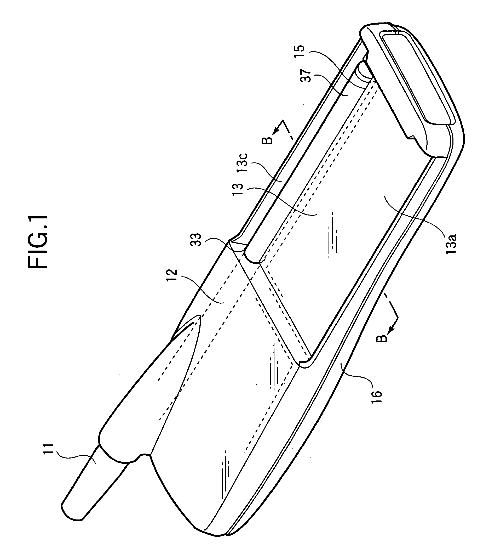
[0026]Hereinafter, a first embodiment of the invention will be explained with reference to FIGS. 1 and 2. FIG. 1 is a perspective view showing the configuration of a portable terminal device according to an embodiment of the invention, showing the portable terminal device with a battery detached, in the state with an antenna contracted so as to store an antenna main body 11 in a tube 37.

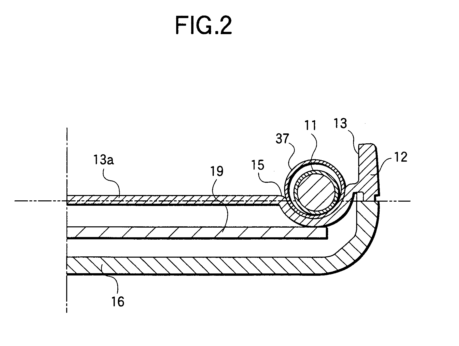
[0027]FIG. 2 is a partial cross-sectional view taken on the line B—B of FIG. 1 on the antenna tube side. A gutter-like antenna tube storage part 15 having a half cylindrical shape, is recessed downward from a flat part 13a of a battery storage part 13, integrally with a rear case 12 of a housing of the portable terminal device. Therefore, the section modulus of the rear case in terms of the strength of materials can be large, and thus deterioration of the rigidity can be prevented even in the case the device main body is made thinner.

[0028]As shown in a cross-sectional view in the axial direction of ...

second embodiment

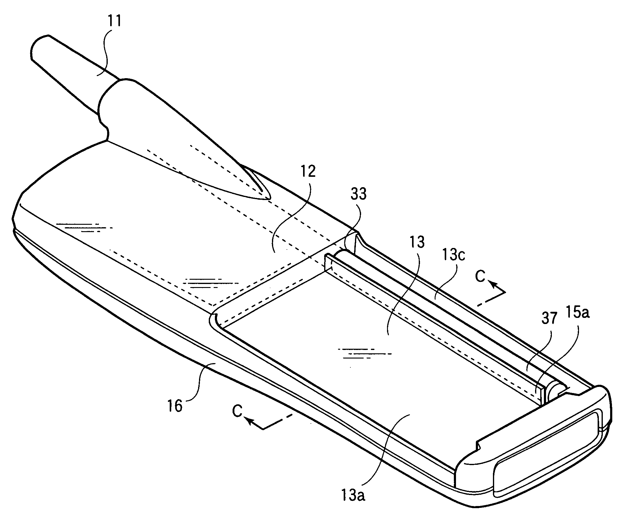
[0029]A second embodiment of the invention will be explained with reference to FIGS. 4 and 5. FIG. 4 is a perspective view showing the configuration of a portable terminal device according to the second embodiment of the invention, and FIG. 5 is a cross-sectional view taken on the line C—C of FIG. 4. It differs from the first embodiment of the invention in that ribs 15a, 15b are formed additionally in the half cylindrical gutter-like antenna tube storage part 15 in the antenna storage direction. Accordingly, the rigidity of the device main body can further be improved as well as the antenna tube 37 can easily be stored in the antenna tube storage part 15 of the rear case and can hardly be detached from the antenna storage part 15 so as to improve the assembly property. The ribs 15a, 15b can be provided both or only one of them can be provided as well.

third embodiment

[0030]A third embodiment of the invention will be explained with reference to FIGS. 6 and 7. FIG. 6 is a perspective view showing the configuration of a portable terminal device according to the third embodiment of the invention, and FIG. 7 is a cross-sectional view taken along the line D—D of FIG. 6. It differs from the first embodiment of the invention in that a protrusion part of the half cylindrical gutter-like antenna tube storage part 15 is formed on the battery side in the battery storage part, and the antenna tube 37 is stored in the recess part of the antenna tube storage part formed on the opposite side with respect to the battery side. As shown in an exploded perspective view of FIG. 8, since the antenna tube 37 can be stored on the same side as the antenna holder receiving part 41, unlike the conventional example, the antenna tube need not be inserted through the hole of the rear case of the housing so that the assembly property can be improved. The antenna tube 37 is fi...


PUM


Abstract

A gutter-like antenna tube storage part having a half cylindrical shape, is recessed downward from a flat part of a battery storage part, integrally with a rear case of a housing of a portable terminal device. Therefore, the section modulus of the rear case in terms of the strength of materials can be large, and thus deterioration of the rigidity can be prevented even in the case the device main body is made thinner.

Description

BACKGROUND OF THE INVENTION[0001]The present invention relates to a portable terminal device, in particular, it relates to that comprising a gutter-like antenna tube storage part in a rear case of a housing, with a rib provided along the antenna storage direction in the antenna tube storage part so as to increase the rigidity of the device main body as well as to improve the assembly property of the device.[0002]As shown in FIG. 11, in conventional portable terminal devices, an antenna tube 37 is placed on a flat part 34a of a battery storage part 34 through a hole 33 provided in a rear case 32 of a housing so as to be interposed and fixed between an engaging rib 34b provided on the flat part 34a of the battery storage part 34 and an inner wall 34c of the rear case.[0003]The state will be explained with reference to FIG. 12. The antenna tube 37 is stored in the rear case 32 of the housing, contacting with the side part of the battery storage part for storing a battery. A short engag...

Claims


Application Information

Patent Timeline
IPC IPC(8): H01Q1/24H01Q1/08H04B1/38H04M1/02
CPCH01Q1/244H04M1/026
Inventor KITAMURA, TOSHIYASUHAMADA, NOBUTOSHIFURUKAWA, KATSUHISA
Owner PANASONIC CORP
Learn More