Flat-plate antenna and method for manufacturing the same

Inactive Publication Date: 2005-07-12
HITACHI METALS LTD
View PDF11 Cites 22 Cited by
  • Summary
  • Abstract
  • Description
  • Claims
  • Application Information

AI Technical Summary

Benefits of technology

[0007]An object of the present invention is to provide a flat-plate antenna and method for manufacturing the same for realizing thinner shape and exce

Problems solved by technology

Especially, accompanied with tendency to compactness of portable terminal itself, an antenna for use in a portable terminal is required to solve problems of installation space and request for satisfying characteristics contradicting to restriction of antenna volume.
Moreover, in a plan of domestic wireless network which has been progressing recently, problem of an antenna size has been arisen, in accordance with installation of an antenna in a personal computer or an electric appliance (hereinafter collectively referred to as “an electric appliance”) or on a wall surface within a room.
However, according to a conventional small-size antenna, firstly, antenna efficiency is inferior due to large dielectric loss of a ceramic diele

Method used


Image

  • Flat-plate antenna and method for manufacturing the same
  • Flat-plate antenna and method for manufacturing the same
  • Flat-plate antenna and method for manufacturing the same

Examples


Example

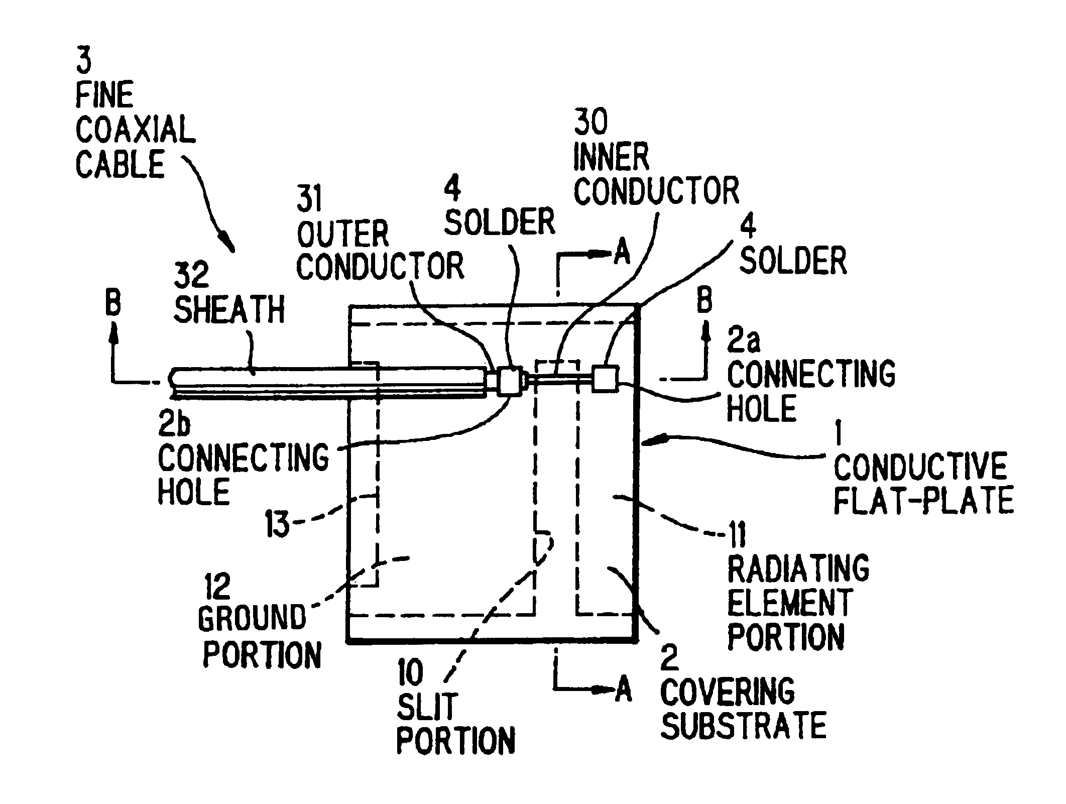
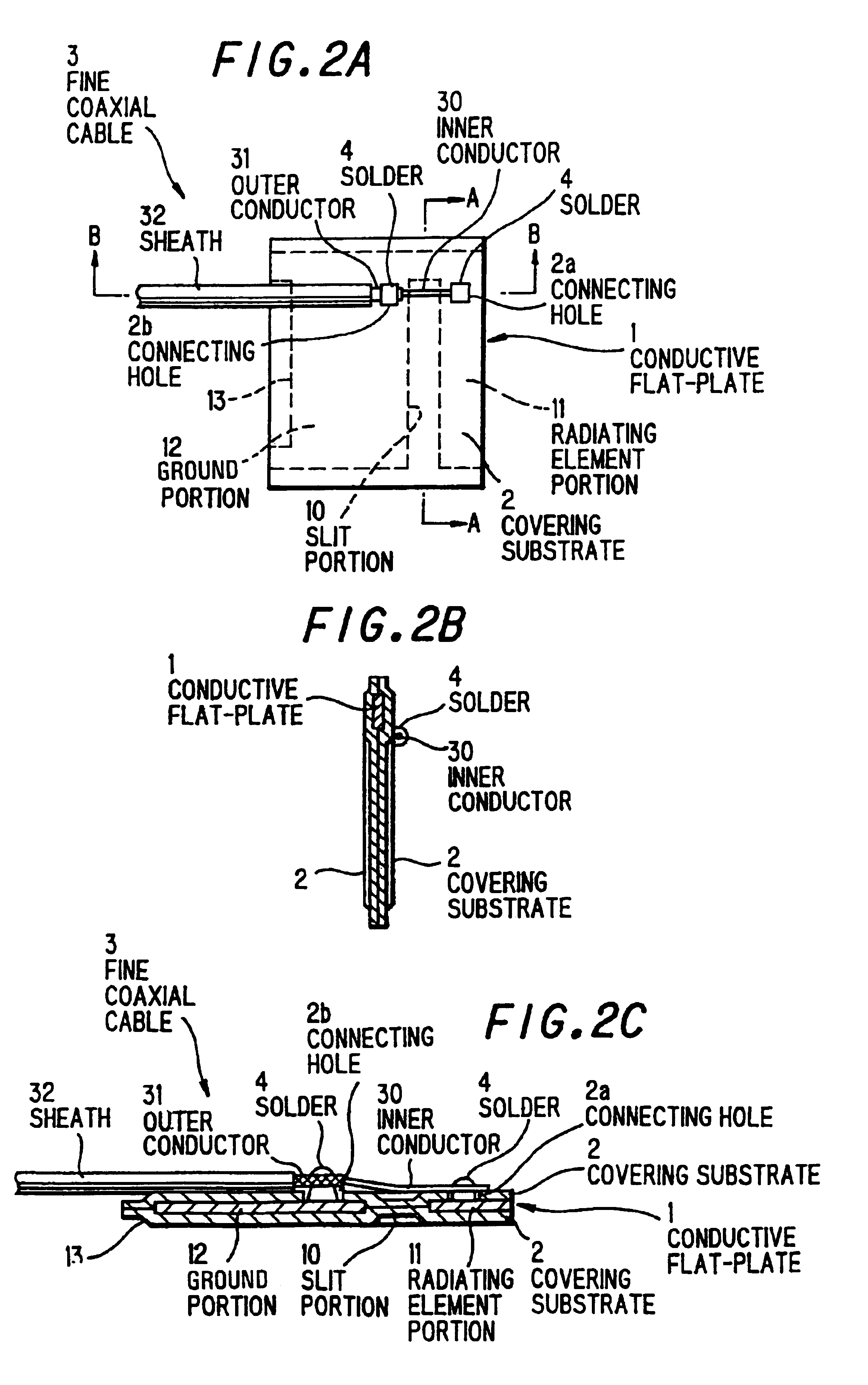
[0019]A flat-plate antenna according to an example of the present invention is shown in FIG. 2(a)-FIG. 2(c). A flat-plate antenna comprises a slit portion 10 having width proportional to frequency band width, a conductive flat-plate 1 having a L shaped radiating element portion 11 disposed on one side of said slit portion 10 and a ground portion 12 disposed on other side of said slit portion 10, a covering substrate 2 covering said conductive flat-plate 1 with a resinous film and a fine coaxial cable 3 supplying power to said conductive flat-plate 1.

[0020]A covering substrate 2 is preferably formed by laminating over a surface of conductive flat-plate 1 with a resinous film. A heat resistant film such as a polyester film is preferably used as a resinous film to reinforce a conductive flat-plate 1 and to prevent deformation of it. Moreover, melting or deformation of a conductive flat-plate 1 caused by heat of solder connecting of a fine coaxial cable 3, or heat from surrounding opera...


PUM

PropertyMeasurementUnit
Electrical conductoraaaaaaaaaa
Widthaaaaaaaaaa

Abstract

A flat-plate antenna includes a conductive flat-plate, a slit portion formed through the conductive flat-plate with width proportional to frequency band width, a radiating element portion disposed one side of the slit portion, a ground portion disposed other side of the slit portion, and a power supply line having a first conductor connected to the radiating element and a second conductor connected to the ground portion.

Description

BACKGROUND OF THE INVENTION[0001]1. Field of the invention[0002]The present invention relates to a flat-plate antenna for installation in an electrical apparatus such as a portable terminal or an electric appliance or on a wall or the like, and method for manufacturing the same, and more specifically, to flat-plate antenna and method for manufacturing the same for realizing thinner shape and excellent productivity, reducing labor for installation in an electrical apparatus or on a wall, and exhibiting desired antenna characteristics stably.[0003]2. Prior Art[0004]In recent years, except large-scale antennas for use in base station or satellite broadcasting, tendency to compactness of various kinds of antennas for use in a potable telephone or a mobile computer (hereinafter collectively referred to as “a portable terminal”) have been progressing. Especially, accompanied with tendency to compactness of portable terminal itself, an antenna for use in a portable terminal is required to ...

Claims


Application Information

Patent Timeline
IPC IPC(8): H01Q9/04H01Q13/10H01Q1/40H01Q13/08H01P11/00
CPCH01Q1/1221H01Q1/38H01Q1/40H01Q9/0421H01Q13/10H01Q13/106H01R9/0515H01Q9/42Y10T29/49016H01R2201/02Y10T29/49121Y10T29/49147H01R4/023
Inventor IKEGAYA, MORIHIKOSUGIYAMA, TAKAHIROTATE, HISASHI
Owner HITACHI METALS LTD
Why Eureka
Try Eureka