Battery, electronic device and arrangement of capacitor in electronic device
A technology of electronic devices and capacitors, applied in capacitors, secondary batteries, primary batteries, etc., can solve problems such as difficulty in thinning and thickness restrictions, and achieve the effect of thinning the overall shape
- Summary
- Abstract
- Description
- Claims
- Application Information
AI Technical Summary
Problems solved by technology
Method used
Image
Examples
Embodiment 1
[0027] (1) Structure of Embodiment 1
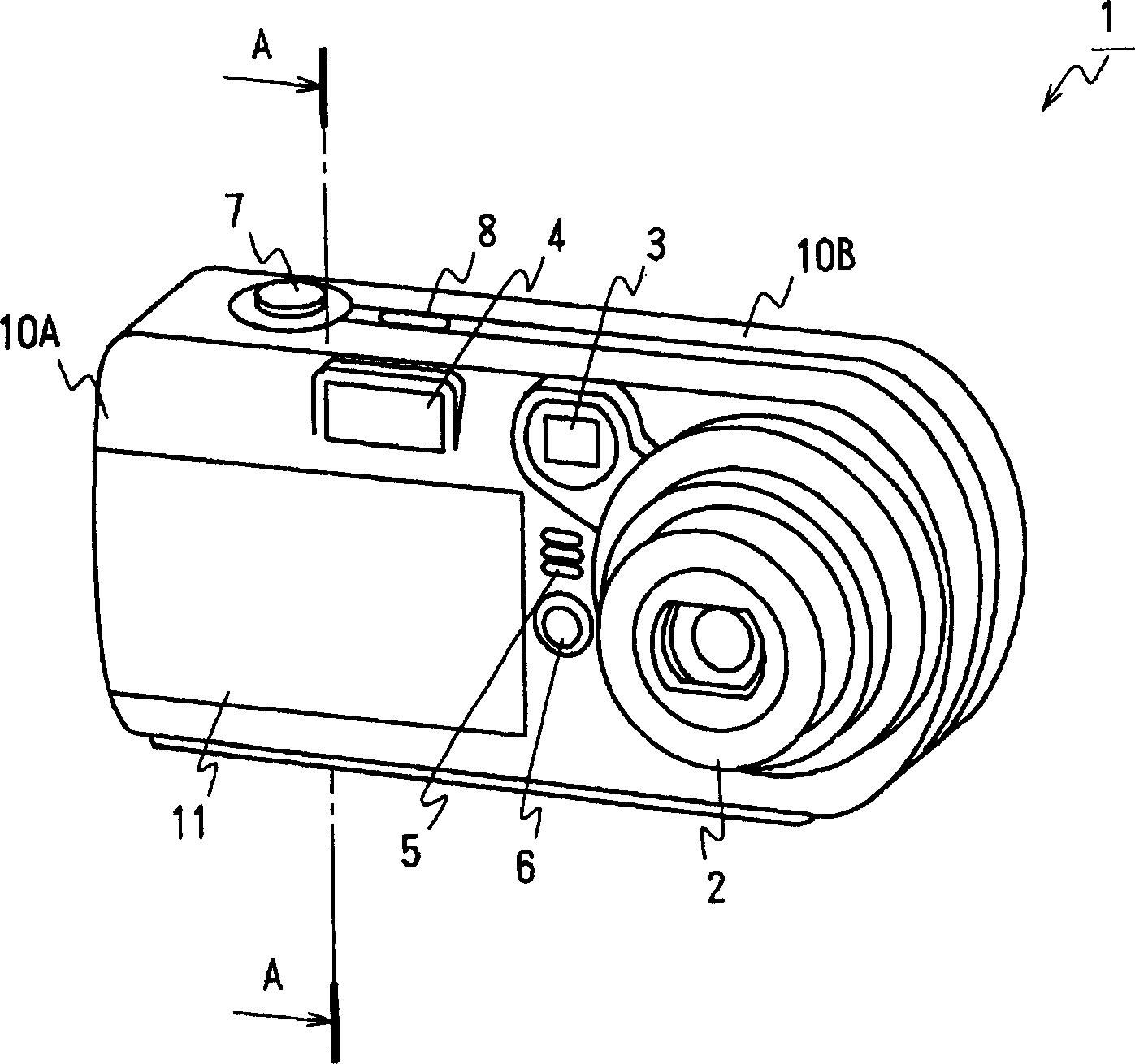
[0028] figure 1 It is a perspective view showing the electronic camera of the portable electronic device according to the first embodiment of the present invention. The electronic camera 1 is formed in a thin, horizontally long rectangular shape. Viewed from the front side, electronic camera 1 is provided with lens 2 at its horizontally long end side, and at the upper end side, is provided with viewfinder window 3, flashlight 4, near lens 2, is provided with microphone 5, Selfie light 6 roughly in the center. As a result, the electronic camera 1 is formed as a substantially rectangular flat member from the center of the front side, except for the left side and the upper end side. The electronic camera 1 is also provided with a shutter button 7 and a power switch 8 on the upper end surface, and a liquid crystal screen, various operation keys, etc. on the back side.
[0029] In this way, the electronic camera 1 is externally formed by a ...
Embodiment 2
[0055] Image 6 It is a connection diagram showing both capacitors and corresponding circuit blocks used in the electronic camera according to Embodiment 2 of the present invention. In this electronic camera, a battery 11 is installed in the same manner as in the above-mentioned first embodiment, and the capacitor 13 of the battery 11 is used for Image 6 circuit block shown. Furthermore, the electronic camera of this embodiment is not only compatible with Image 6 Except for the difference in the structure, it has the same structure as the electronic camera of the first embodiment.
[0056] That is, in this electronic camera, the DC-DC converter 48 mounted on the wiring board 32 boosts the power of the battery 11 to generate power of a required voltage, and the capacitor 13 is used for smoothing the power.
[0057] Even in the case where a large-capacity capacitor for smoothing is provided as in the present embodiment, the same effect as that of the first embodiment can be...
Embodiment 3
[0059] Figure 7 It is a connection diagram showing both the battery and the corresponding circuit block used in the electronic camera according to Embodiment 3 of the present invention. In this electronic camera, a battery 11 is installed in the same manner as in the above-mentioned first embodiment, and the capacitor 13 of the battery 11 is used for Figure 7 circuit block shown. Furthermore, the electronic camera of this embodiment is not only compatible with Figure 7 Except for the difference in the structure, it has the same structure as the electronic camera of the first embodiment.
[0060] That is, in this electronic camera, the capacitor 13 is used for decoupling the power supply of the battery 11 input to the wiring board 32, and the drop of the power supply voltage caused by the instantaneous current is alleviated.
[0061] As in the present embodiment, the same effect as that of the first embodiment can be obtained even when the drop in the power supply voltage...
PUM
 Abstract
Description
Claims
Application Information
 - R&D
- Intellectual Property
- Life Sciences
- Materials
- Tech Scout
- Unparalleled Data Quality
- Higher Quality Content
- 60% Fewer Hallucinations
Browse by: Latest US Patents, China's latest patents, Technical Efficacy Thesaurus, Application Domain, Technology Topic, Popular Technical Reports.
© 2025 PatSnap. All rights reserved.Legal|Privacy policy|Modern Slavery Act Transparency Statement|Sitemap|About US| Contact US: help@patsnap.com


