Network node failover using multicast address or port

a network node and multicast address technology, applied in the field of network failures, can solve problems such as packet ordering that is not guaranteed, packet rejection, and packets that are not guaranteed to be received by group members correctly

a network node and multicast address technology, applied in the field of network failures, can solve problems such as packet ordering that is not guaranteed, packet rejection, and packets that are not guaranteed to be received by group members correctly

US6944786B2Inactive Publication Date: 2005-09-13LENOVO GLOBAL TECH INT LTD

Image

  • Network node failover using multicast address or port
  • Network node failover using multicast address or port
  • Network node failover using multicast address or port

Examples


Embodiment Construction

Overview

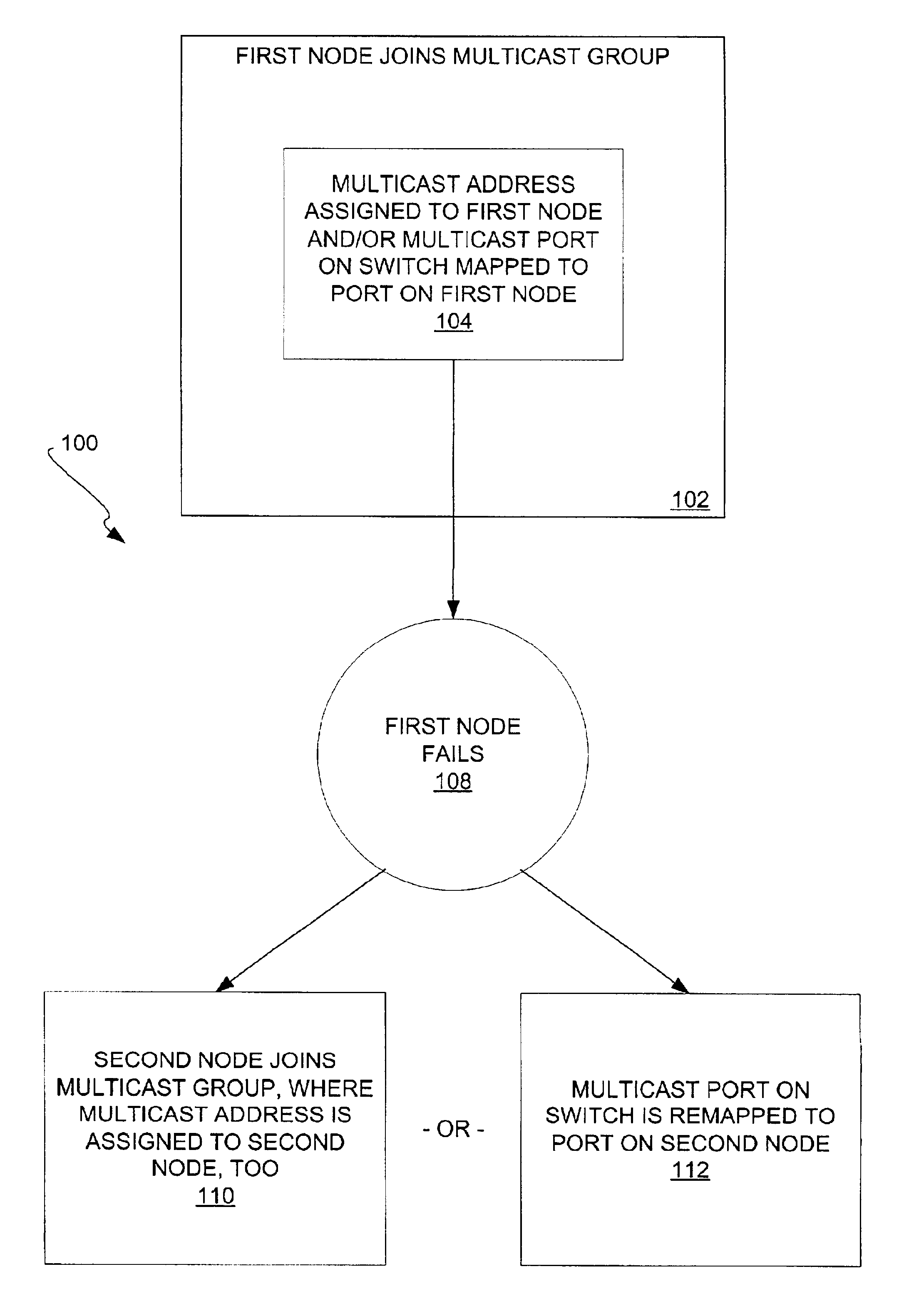
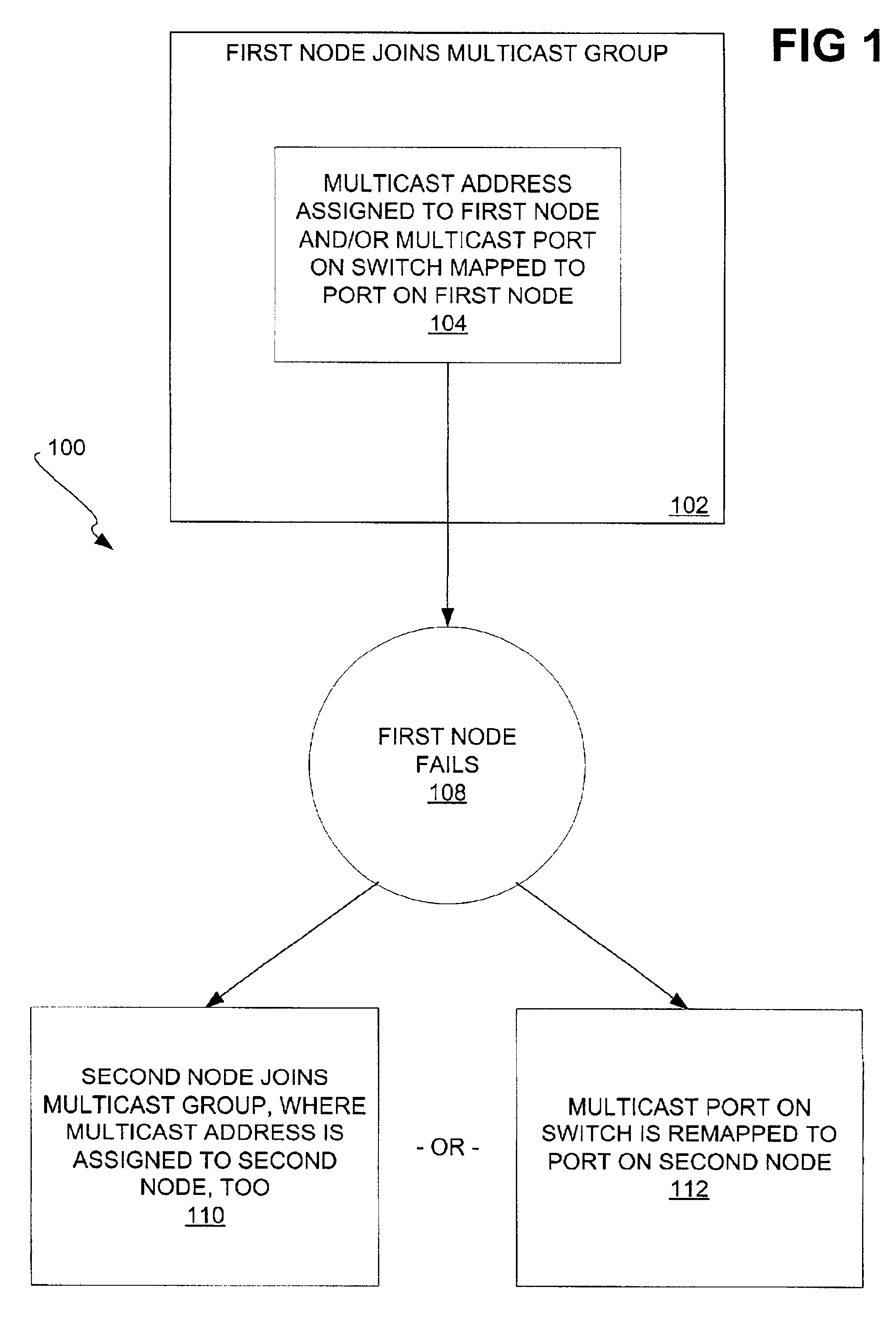
[0024]FIG. 1 shows a method 100 according to a preferred embodiment of the invention. A first node of a network initially joins a multicast group (102). The multicast group has a multicast address. At least one of two actions is performed (104), depending on whether a switch of the network supports multicasting. If the switch supports multicasting, which is considered a first mode, then the multicast address is assigned to the first node. Communication to the multicast address may then be automatically directed to the first node, where the network may have been previously manually or automatically set up to achieve such communication. If the switch does not support multicasting, which is considered a second mode, then a multicast port on a switch of the network is mapped to, or associated with, a port on the first node. Communication to the multicast address may then be directed to the port on the first node from the multicast port on the switch, where the switch does not su...


PUM


Abstract

The failover of nodes within networks, using a multicast address or a multicast port, is disclosed. A first node of a network joins a multicast group having a multicast address, which is assigned to the first node. Communication to the first node is achieved via communication to the multicast address, and / or through a multicast port on a switch of the network mapping to a port on the first node. When the first node fails, one of two actions occurs. First, a second node of the network may join the multicast group, such that the multicast address is assigned to the second node, and the second node handles communication to the multicast address. Second, the multicast port on the switch may be remapped to a port on the second node, so that communication to the multicast address is directed to the port on the second node.

Description

BACKGROUND OF THE INVENTION[0001]1. Technical Field[0002]This invention relates generally to networks, such as Infiniband networks, and more particularly to failover of nodes within such networks.[0003]2. Description of the Prior Art[0004]Input / output (I / O) networks, such as system buses, can be used for the processor of a computer to communicate with peripherals such as network adapters. However, constraints in the architectures of common I / O networks, such as the Peripheral Component Interface (PCI) bus, limit the overall performance of computers. Therefore, new types of I / O networks have been proposed.[0005]One new type of I / O network is known and referred to as the InfiniBand network. The InfiniBand network replaces the PCI or other bus currently found in computers with a packet-switched network, complete with one or more routers. A host channel adapter (HCA) couples the processor to a subnet, whereas target channel adapters (TCAs) couple the peripherals to the subnet. The subne...

Claims


Application Information

Patent Timeline
13 Sep 2005
Publication
US6944786B2
IPC
G06F11/20; H04L12/18; H04L12/24; G06F13/00; H04L12/56
CPC
G06F11/20; H04L12/185; H04L12/1877; H04L41/0663
Inventors
KASHYAP, VIVEK