
Method and apparatus for increasing spatial resolution of a pet scanner

a technology of positron emission tomography and scanners, applied in the field of pet scanners, can solve the problems of significant reduction of detecting efficiency, reduced resolution compared with conventional gamma cameras, and inability to achieve image resolution higher than the intrinsic spatial resolution of detectors, etc., and achieve the effect of increasing the resolution of an imag

Inactive Publication Date: 2005-09-20
WASHINGTON UNIV IN SAINT LOUIS
View PDF23 Cites 28 Cited by
  • Summary
  • Abstract
  • Description
  • Claims
  • Application Information

AI Technical Summary

Benefits of technology

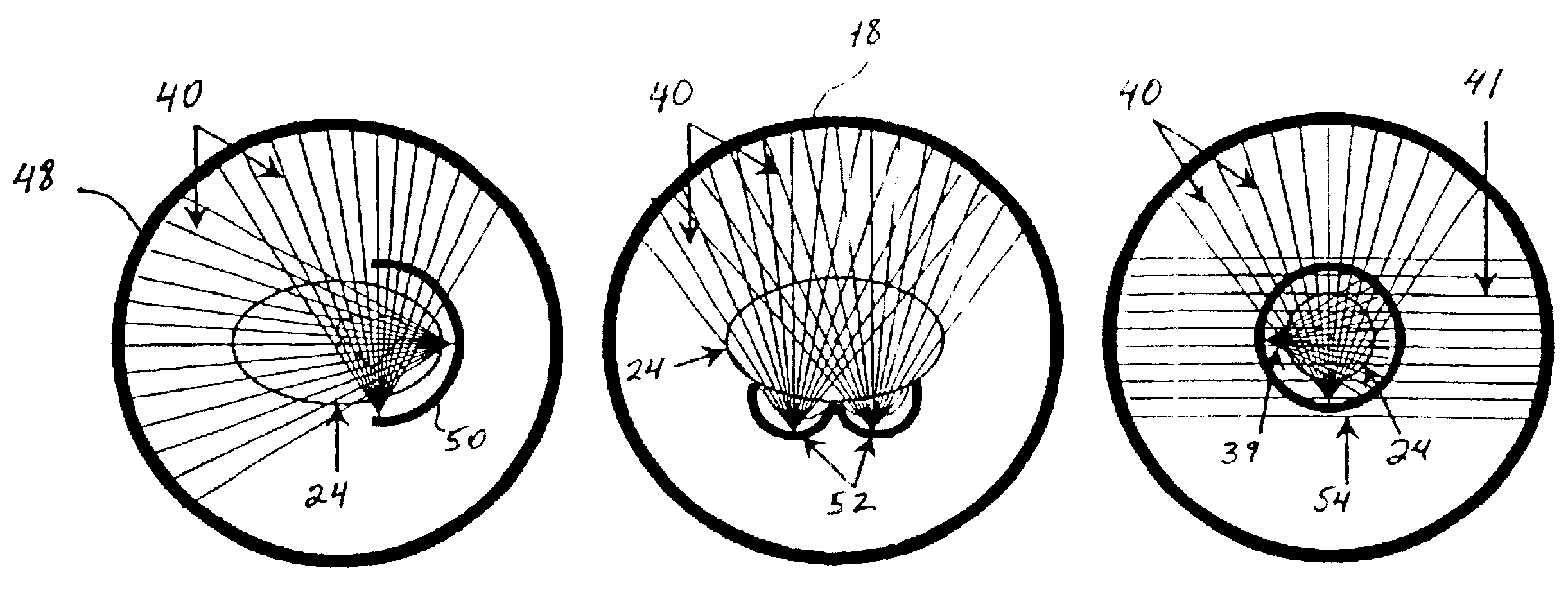
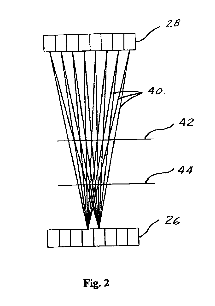
[0017]In yet another aspect of the invention, a method of PET scanning is provided using a PET scanner comprising opposing first and second detector arrays that are each formed as an arc of a circle, with the radius of the arc of the first detector being less than the radius of the arc of the second detector array. The detectors of the first detector array have an intrinsic spatial resolution that is equal to or better than the intrinsic spatial resolution of the detectors of the second detector array. The method comprises centering the region of interest of the object at a point between the first and second detector arrays which is at least about ten percent closer to the first detector array than to the second detector array, and scanning the object with the scanner.
[0018]In another aspect, the present invention includes a method of increasing resolution of an image of a region of interest of an object provided by a positron emission tomography scanner comprising first and second circular concentric detector arrays. The detectors of the first detector array have an intrinsic spatial resolution that is equal to or better than the intrinsic spatial resolution of the detectors of the second detector array. The method comprises centering the region of interest of the object at a point inside the first and second detector arrays and scanning the object with the scanner.
[0019]In yet another aspect the present invent

Problems solved by technology

However, conventional PET scanners have been unable to achieve image resolution higher than the detector intrinsic spatial resolution regardless of the type of gamma-ray detector employed.
The drawback of this design is a significant reduction of detecting efficiency.
The disadvantage of a Compton camera is its reduced resolution compared with a conventional gamma camera.

Method used


Image

  • Method and apparatus for increasing spatial resolution of a pet scanner
  • Method and apparatus for increasing spatial resolution of a pet scanner
  • Method and apparatus for increasing spatial resolution of a pet scanner

Examples


Embodiment Construction

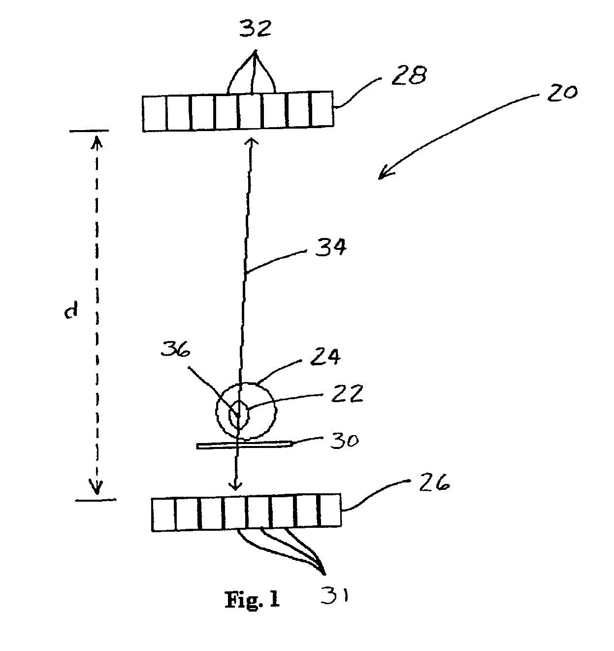
[0038]Referring now to the drawings and in particular to FIG. 1, a positron emission tomography (“PET”) scanner is designated in its entirety by the reference character 20. The scanner 20 provides an image of a region of interest 22 of an object 24. The scanner 20 comprises opposing first and second detector arrays 26, 28, respectively, spaced by a distance d and a stage 30 for holding the object 24 between the arrays. The first detector array 26 is formed from a series of adjacent gamma-ray photon detectors 31, while the second detector array 28 is formed from a series of adjacent gamma-ray photon detectors 32. The detectors 31 of the first detector array 26 have intrinsic spatial resolutions that are equal to or preferably better than intrinsic resolutions of the detectors 32 of the second detector array 28. Better intrinsic spatial resolution, in other words resolution capable of distinguishing smaller structures of the object, may be achieved through a variety of known methods i...


PUM


Abstract

A method and apparatus for increasing the resolution of a Positron Emission Tomography scanner. The method and apparatus comprise elements and acts for centering a region of interest of an object at a point between first and second detector arrays which is at least about ten percent closer to the first detector array than to the second detector array.

Description

[0001]This application is based upon and claims priority from a U.S. Provisional Application No. 60 / 394,135 filed on Jul. 5, 2002.BACKGROUND OF THE INVENTION[0002]The present invention relates generally to Positron Emission Tomography (“PET”) scanners, and more particularly to a method of PET scanning and a PET scanner apparatus having increased image resolution.[0003]Positron Emission Tomography (“PET”) is an imaging technique that provides three-dimensional tomographic images of a distribution of positron-emitting isotopes within an object. The object is usually a living human or animal, and the images provide a visual depiction of tissue differences within different portions of the object. A PET procedure involves the introduction of radiolabeled tracing pharmaceuticals into the object, usually through injection or inhalation. The type of pharmaceuticals depends on the function of the tissue under investigation. As the radiolabeled tracing element in the pharmaceutical decays, it...

Claims


Application Information

Patent Timeline
IPC IPC(8): G01T1/164G01T1/17G01T1/161G01T1/00A61BG01T1/29
CPCG01T1/2985
Inventor TAI, YUAN-CHUAN
Owner WASHINGTON UNIV IN SAINT LOUIS
Learn More