
Rocket engine nozzle that is steerable by means of a moving diverging portion on a cardan mount

a technology of a diverging portion and a nozzle is applied in the direction of rocket engine plants, machines/engines, hot gas positive displacement engine plants, etc., which can solve the problems of difficult to make laminated abutments that can withstand a very wide range of temperatures, and can be subjected to tension forces

Inactive Publication Date: 2005-09-27
GERAKL
View PDF14 Cites 18 Cited by
  • Summary
  • Abstract
  • Description
  • Claims
  • Application Information

AI Technical Summary

Benefits of technology

[0007]An object of the invention is to provide a steerable nozzle for a rocket engine that does not present the drawbacks of the state of the art using a connection via the above-mentioned laminated spherical abutment, and in particular to propose a jointed mount that is robust and reliable, while also providing gas-tightness at the contacting surfaces for any desired orientation of the nozzle.
[0010]By means of the resilient return force that is exerted, a relatively stable force pressing the spherical surfaces against each other can be ensured regardless of the displacements performed during operation, thus enabling actuation to take place in any direction without affecting the gas-tightness between these spherical surfaces.
[0016]Compared with prior art devices using a laminated spherical abutment, the steerable nozzle assembly of the present invention presents significant advantages:
[0017]it is more robust in the face of environmental conditions and aging;
[0018]it enables large thrust-deflection angles to be obtained by using larger spherical contact areas, which combines with the phenomenon of amplified thrust deflection that is inherent to devices having a moving diverging portion and that is due to aerodynamic effects internal to the nozzle;
[0020]it makes it possible to avoid not only a laminated spherical abutment, which is a component that is relatively expensive, but also to omit the thermal protection that needs to be associated therewith.

Problems solved by technology

Such a device enables the nozzle to swivel to a limited extent relative to the casing by deformation of the resilient layers in shear.
Unfortunately, in certain configurations, the laminated abutment can be subjected to tension forces.
In addition, laminated abutments are sensitive to aging and it is difficult to make laminated abutments that are capable of withstanding a very wide range of temperatures.
Such a mount avoids the drawbacks of mounts having laminated spherical abutments, but the problem to be solved is that of providing gas-tightness between the contacting spherical surfaces for all orientations of the diverging portion of the nozzle.
Those tests have shown that the concept is viable but with limitations on control in the pitch and yaw planes, with the ball being pressed against the socket by prestressed actuators.

Method used


Image

  • Rocket engine nozzle that is steerable by means of a moving diverging portion on a cardan mount
  • Rocket engine nozzle that is steerable by means of a moving diverging portion on a cardan mount
  • Rocket engine nozzle that is steerable by means of a moving diverging portion on a cardan mount

Examples


Embodiment Construction

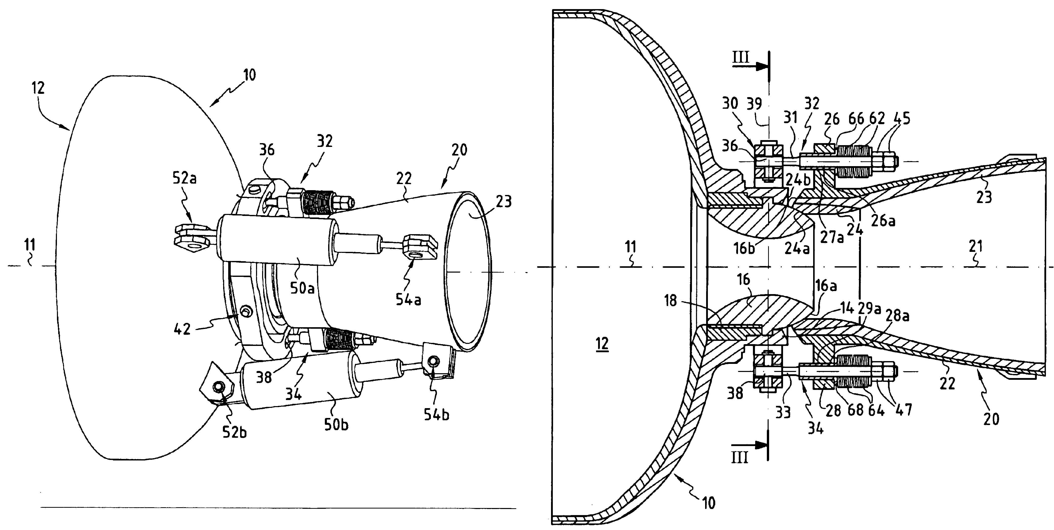
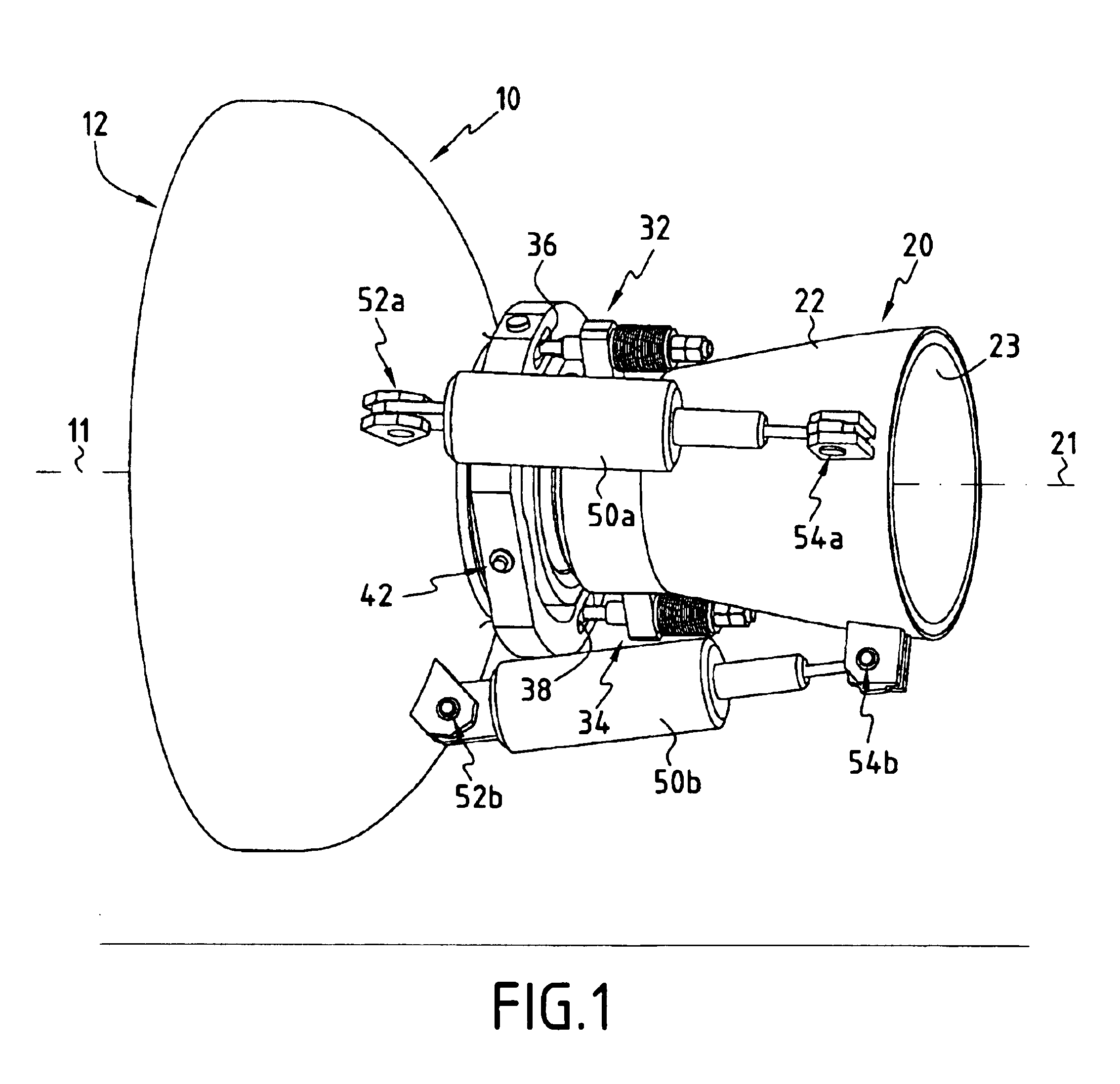
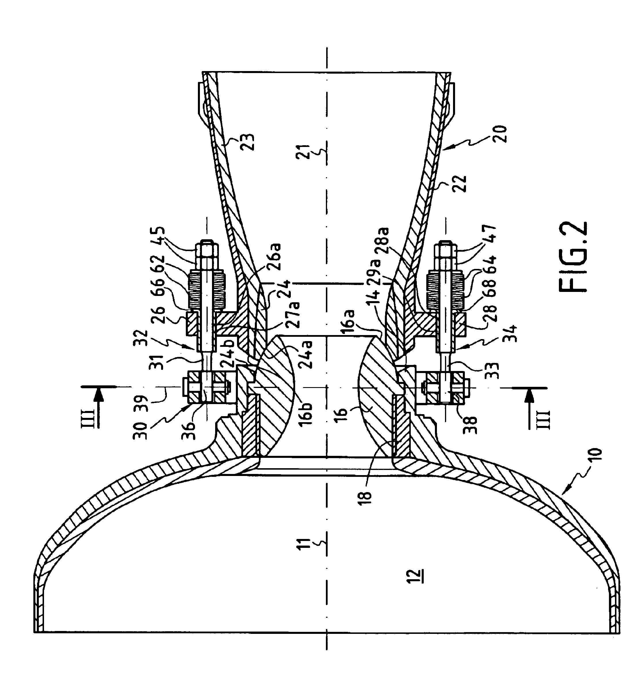
[0025]FIGS. 1 to 3 are diagrams showing a rocket engine having a casing 10 surrounding a combustion chamber 12 in which there is received a block of solid propellant (not shown). The chamber 12 opens out through its rear end wall 14 into the front of a nozzle that comprises a throat part 16 and a diverging portion 20.

[0026]The throat part 16 defines not only the nozzle throat proper, but also the converging portion and the beginning of the diverging portion, and it is fastened, e.g. by being screwed into a ring 18 that is fixed to the end wall 14 of the casing, so as to be secured to the end wall 14.

[0027]The throat part 16 is typically made of C / C composite material, and the ring 18 is typically made of insulating composite material. Thermal protection layers are provided on the inside face of the casing. Such a combustion chamber structure is well known in itself.

[0028]The diverging portion 20 of the nozzle (or at least a fraction thereof) is movable, being mounted on a static por...


PUM


Abstract

The nozzle comprises a moving diverging portion (20) and a static portion (16) secured to the rear end wall of the combustion chamber (12) of the engine. A cardan mount jointed link device connects the moving diverging portion of the nozzle to the static portion, the moving diverging portion and the static portion being in mutual contact via respective spherical surfaces (24a, 16a), and an actuator device (50a, 50b) acts on the moving diverging portion of the nozzle so as to be able to vary the direction of the thrust vector of the engine by modifying the orientation of the nozzle with sliding of the spherical surfaces one on the other. Resilient return means (62, 64) are interposed between the moving diverging portion (20) of the nozzle and the static portion (16) and act on the moving diverging portion in order to urge it towards the static portion so as to keep the spherical surfaces (24a, 16a) in mutual contact for any desired orientation of the nozzle.

Description

[0001]This application is a 371 national phase filing of PCT / FR2003 / 002067 file Jul. 3, 2003, and claims priority to a French application No. 02 / 08370 filed Jul. 4, 2002.BACKGROUND OF THE INVENTION[0002]The invention relates to steerable nozzles for rocket engines.[0003]The field of application of the invention is more particularly but not exclusively that of missiles, in particular tactical missiles having a diameter of less than about 500 millimeters (mm).[0004]A steerable-nozzle rocket engine comprises a casing defining a combustion chamber that opens out through a rear end wall, at least one nozzle comprising a moving diverging portion and a static portion, a jointed link device connecting the moving diverging portion and the static portion, and an actuator device acting on the nozzle to change its orientation, and consequently to change the direction of the thrust vector produced by combustion gas being ejected from the chamber.[0005]A known jointed link device uses a laminated...

Claims


Application Information

Patent Timeline
Patent Type & Authority Patents(United States)
IPC IPC(8): F02K9/00F02K9/84F02K1/00
CPCF02K9/84
Inventor BERDOYES, MICHELDUMORTIER, ANDREBIZ, PHILIPPEHERVIO, ANTOINE
Owner GERAKL
Learn More