Inline pressure sensor

a pressure sensor and inline technology, applied in the direction of instruments, structural/machine measurement, fluid pressure measurement using elastically deformable gauges, etc., can solve the problems of unfavorable liquid pool, dead volume (liquid pool), etc., to reduce or eliminate waste of liquid members, and eliminate or minimize dead volume

Active Publication Date: 2005-09-27
SURPASS IND
View PDF14 Cites 11 Cited by
  • Summary
  • Abstract
  • Description
  • Claims
  • Application Information

AI Technical Summary

Benefits of technology

[0013]According to the inline pressure sensor having the above structure, the second liquid member flow path is formed such that a distance between a pressure sensing surface on the pressure sensing section and a surface of the housing which faces to the pressure sensing section be smaller than an inner diameter of the piping section. Therefore, it is possible to eliminate or minimize the dead volume which causes a liquid pool in which the liquid member remains thereinside undesirably because a necessary cross sectional area can be realized. That is, it is necessary to form an area for sensing the pressure larger than a cross sectional area in the flow path so as to realize a desirable sensitivity in the pressure sensor in the sensor section. Therefore, it is preferable that the cross sectional area of the second liquid member flow path be approximately the same as the cross sectional area in the first liquid member flow path and the cross sectional area in the third liquid member flow path by minimizing the distance between a pressure sensing surface on the pressure sensing section and a surface of the housing which faces to the pressure sensing section.
[0014]As explained above, according to the inline pressure sensor of the present invention, the flow path in the housing to which the liquid member flowing in the piping section is lead is formed such that the first liquid member flow path which switches a direction of the liquid member from the aligned flow path to the pressure sensing section, a second liquid member flow path for flowing the liquid member along the pressure sensing section; and a third liquid member flow path for switching a direction of the liquid member from the pressure sensing section to the aligned flow path are connected in an approximate convex alignment viewed in cross section in the housing. Therefore, it is possible to eliminate or minimize the dead volume which causes a liquid pool in which the liquid member remains thereinside undesirably. Accordingly, it is possible to prevent the liquid member from decomposing while remaining thereinside for a long period, which is undesirable. Also, a superior effect is realized in that it is possible to reduce or eliminate waste of the liquid member.
[0015]Furthermore, according to the above second liquid member flow path, it is possible to form a distance between a pressure sensing surface on the pressure sensing section and a surface of the housing which faces to the pressure sensing section to be smaller than an inner diameter of the piping section. Therefore, it is possible to eliminate or minimize the dead volume which causes a liquid pool in which the liquid member remains thereinside undesirably because a necessary cross sectional area can be realized.

Problems solved by technology

However, in such a single-port pressure sensor, the branching piping section causes a dead volume (liquid pool) in which the liquid member remains undesirably.
In such a case, there is a problem if the liquid member decomposes.
Also, if an expensive liquid member flows in the piping section, the dead volume in which the liquid member remains undesirably may cause a substantial amount of wasted liquid member; thus, there is a problem in that the unnecessary expense may be incurred.
Therefore, such an inner casing space may cause a liquid pool in which the liquid member remains undesirably.
If an expensive liquid member is circulated, such a liquid member remaining thereinside increases the dead volume; thus, more liquid member is necessary.
Therefore, such a dead volume may cause a substantial amount of waste liquid member; thus, there is a problem in that a unnecessary expense may be incurred.
Also, such a liquid member remaining thereinside is not preferable because the liquid member which is supposed to be used for a beverage or a medicine decomposes while remaining thereinside for a long period and this is not desirable.

Method used


Image

  • Inline pressure sensor
  • Inline pressure sensor
  • Inline pressure sensor

Examples


Embodiment Construction

[0021]Embodiments for a pressure sensor of the present invention are explained with reference to drawings below.

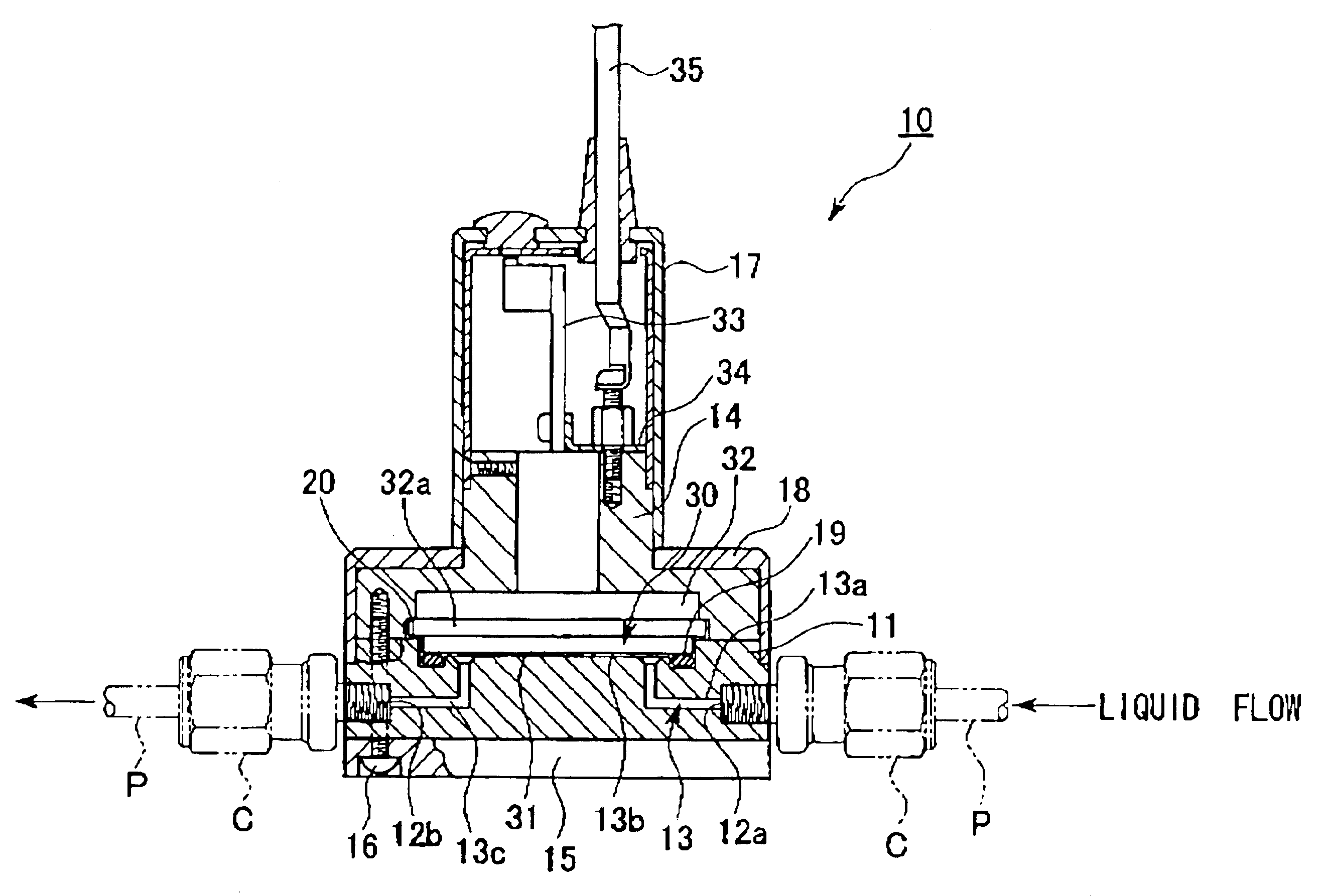
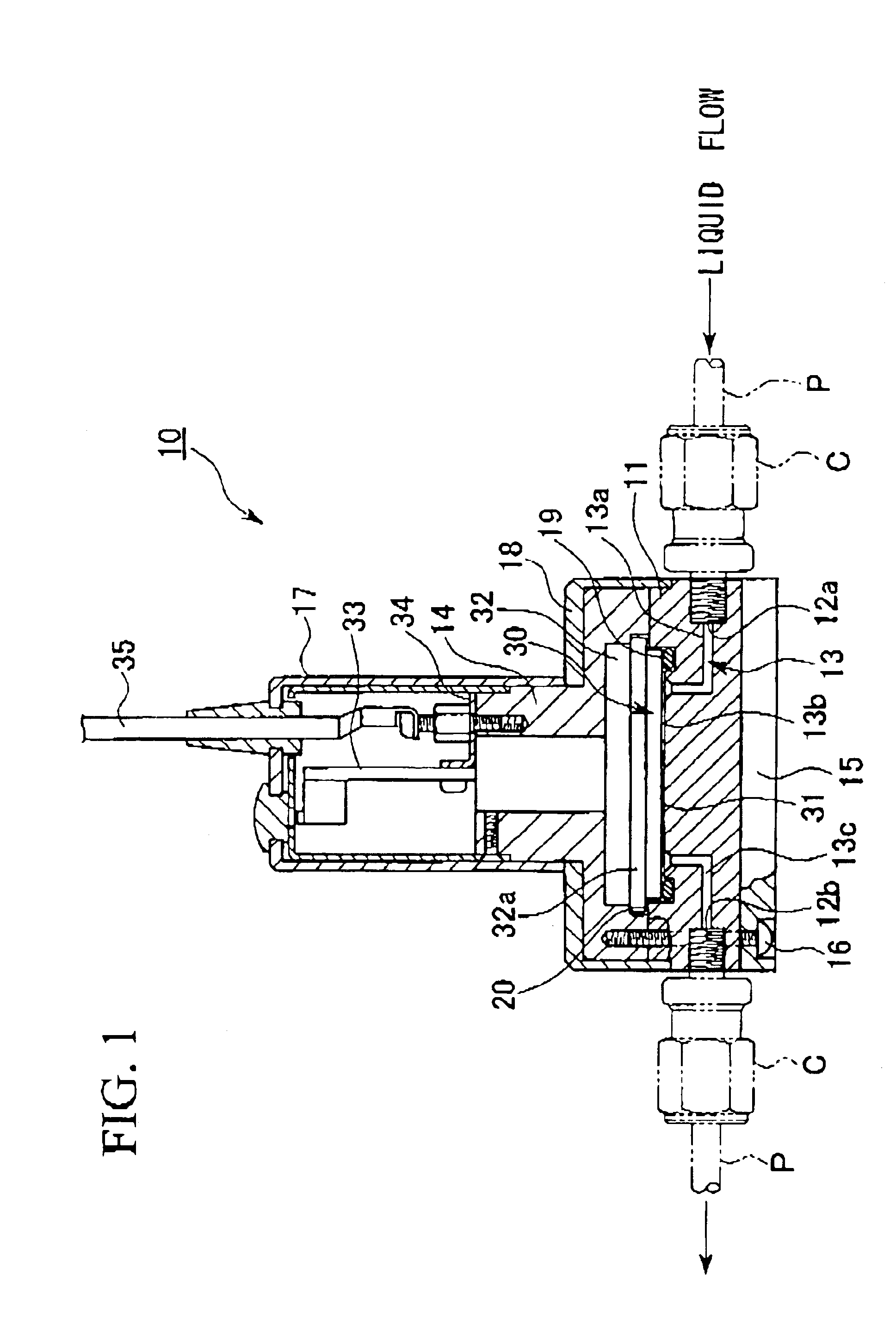
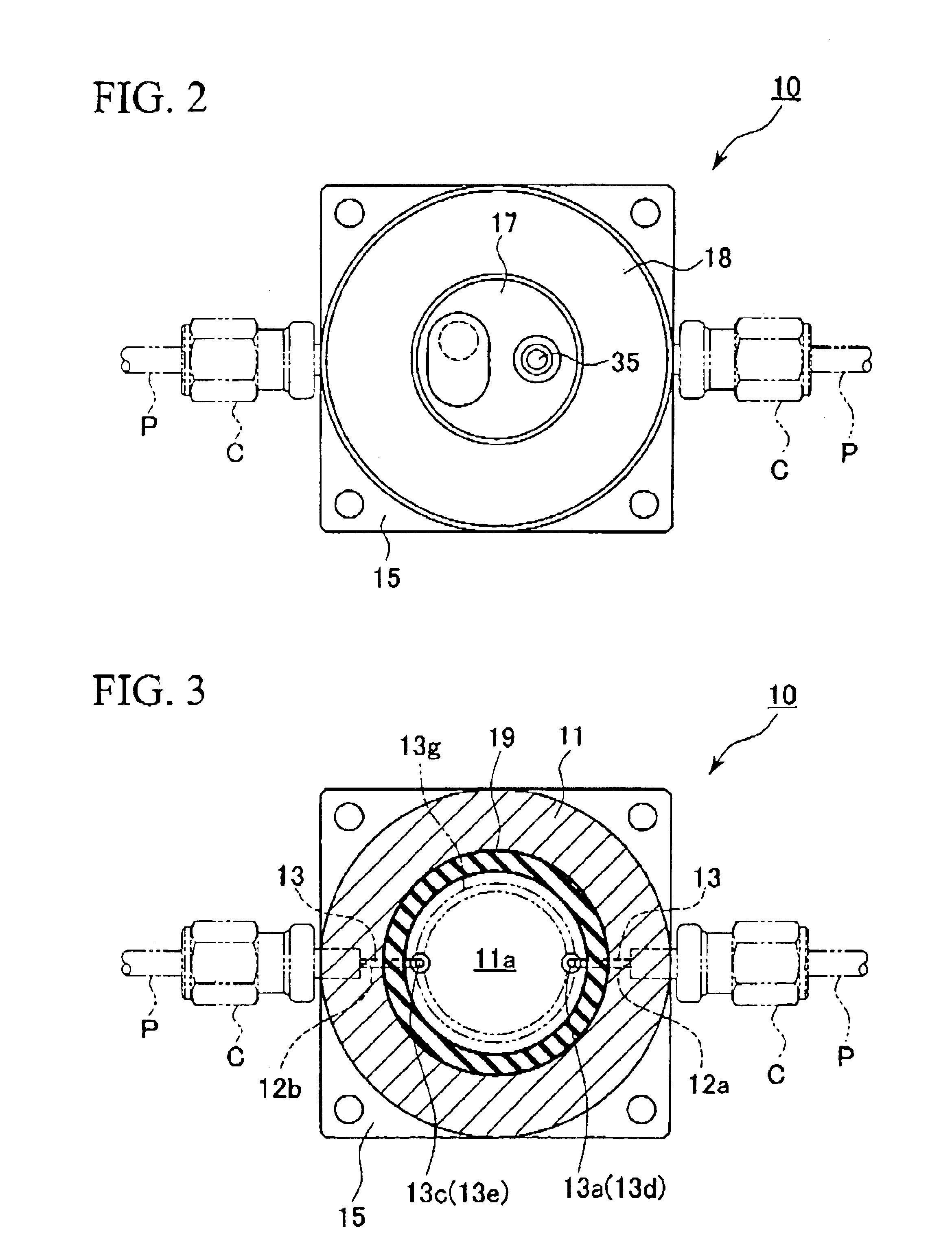
[0022]An inline pressure sensor (hereinafter called a “pressure sensor”) 10 shown in a cross section in FIG. 1 measures a pressure in a liquid member such as a liquid or a gas (hereinafter called a “liquid member”) which flows in a liquid member circuit. The inline pressures sensor 10 is connected to a tube which forms a circuit or a piping section P such as a pipe via a coupling member such as a coupling section C. A pair of coupling ports 12a and 12b which introduce the liquid member of which pressure is supposed to be detected into the housing 11 so as to pass therethrough are formed in the housing 11 having a round cross section forming a part of an external view of the pressure sensor 10 so as to be aligned with the piping section P. The cross sectional area of the coupling ports 12a and 12b is the same as the inner cross sectional area of the piping section P. Here, ...


PUM

PropertyMeasurementUnit
inner diameteraaaaaaaaaa
stressaaaaaaaaaa
distanceaaaaaaaaaa

Abstract

A pressure sensing section and a sensor element are provided in a housing. A pair of coupling ports 12a and 12b are formed at both ends of the housing so as to be aligned with the piping section. A flow path is formed in approximate convex such that the first flow path which switches the flowing direction of the liquid member from an aligned piping section to the pressure sensing section, the second flow path through which the liquid member flows along the pressure sensing section, and the third flow path 13c which switches the flowing direction of the liquid member from the pressure sensing section to the aligned piping section are connected. By doing this, it is possible to provide an inline pressure sensor in which a dead volume as an undesirable liquid pool can be minimized.

Description

[0001]Priority is claimed on Japanese Patent Application No. 2003-176422, filed Jun. 20, 2003, the content of which is incorporated herein by reference.BACKGROUND OF THE INVENTION[0002]1. Field of the Invention[0003]The present invention relates to an inline pressure sensor for measuring a pressure in a liquid member.[0004]2. Description of Related Art[0005]Conventionally, a pressure sensor has been used for measuring a pressure in a liquid member (liquid or gas) which flows in a piping section. Such a pressure sensor is commonly called a single-port pressure sensor which is attached to a branching piping section which is branched from the piping section for flowing the liquid member. However, in such a single-port pressure sensor, the branching piping section causes a dead volume (liquid pool) in which the liquid member remains undesirably. In such a case, there is a problem if the liquid member decomposes. Also, if an expensive liquid member flows in the piping section, the dead v...

Claims


Application Information

Patent Timeline
Patent Type & Authority Patents(United States)
IPC IPC(8): G01L19/00G01L19/06
CPCG01L19/0023
Inventor IMAI, HIROSHI
Owner SURPASS IND
Why Eureka
Try Eureka