Inline pulsation damper system

a damper and pulsation technology, applied in the field of dampers, can solve the problems of large device volume, high cost, and fuel line vibrating against the body of the vehicle, and achieve the effect of high density

Inactive Publication Date: 2005-09-27
DELPHI TECH INC
View PDF9 Cites 49 Cited by
  • Summary
  • Abstract
  • Description
  • Claims
  • Application Information

AI Technical Summary

Problems solved by technology

It is known that pulsations generated by the actuation of the fuel injectors can be transmitted from the engine to the body of a vehicle by a prior art rigid fuel line extending therebetween, causing the fuel line to vibrate against the body of the vehicle and thereby generate audible and undesirable noise.
However, such devices can be bulky, can be relatively costly, and may require recharging or other servicing during their anticipated life span.

Method used


Image

  • Inline pulsation damper system
  • Inline pulsation damper system

Examples


Embodiment Construction

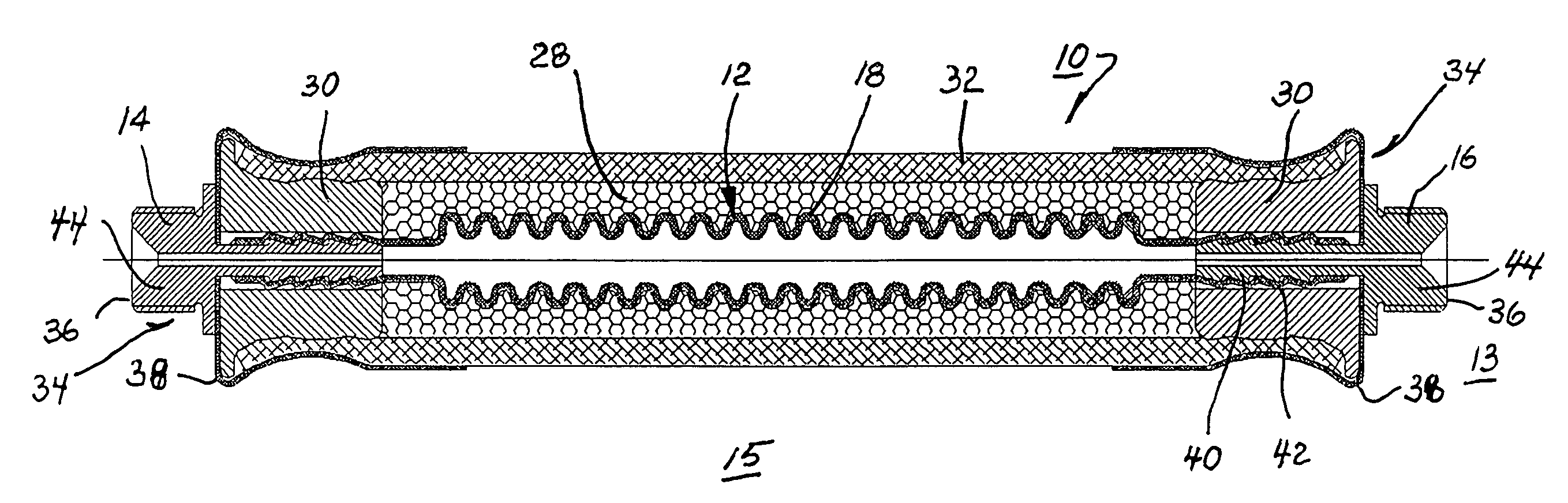
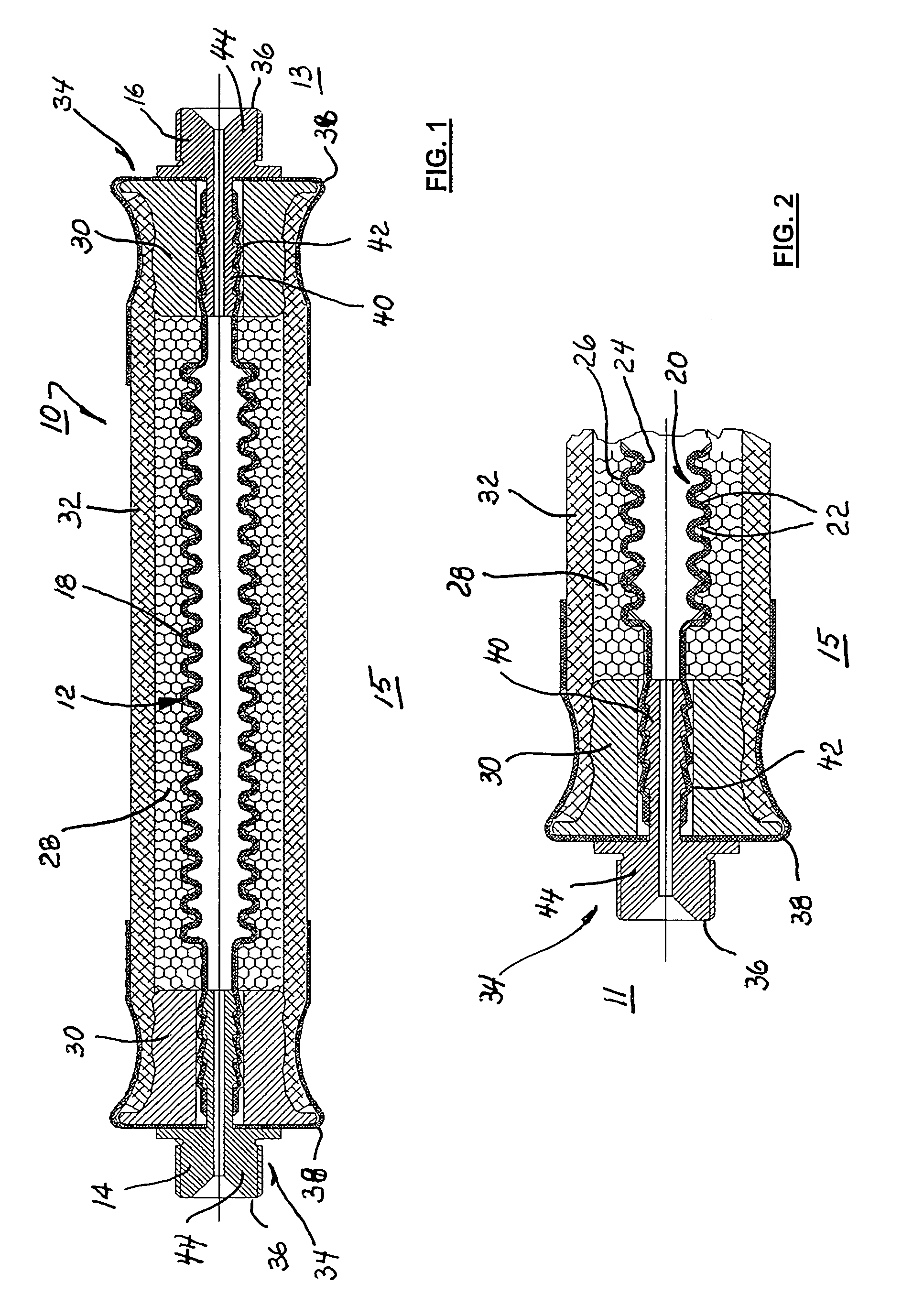
[0010]Referring to FIGS. 1 and 2, numeral 10 generally indicates an exemplary embodiment of an inline hydraulic pulsation damper system in accordance with the invention. Damper system 10 includes hydraulic tubing element 12 having cylindrical inlet and outlet end portions 14, 16 at opposite ends of a flexible, convoluted central portion 18. The convoluted portion of tubing 12 is also referred to herein as “accordionated.” Central portion 18 comprises a plurality of sequentially-connected ring-like convolutions 20 having opposite flexible sides 22 extending between inner and outer diameters 24, 26, respectively. The illustrated convolutions 20 are generally V-shaped in cross-section but they may be made with other configurations having sides capable of flexing to expand and contract the volume of central portion 18 in response to pressure pulsations within tubing 12. The inner and outer diameter bends at diameters 24, 26 may be sharp, discontinuous creases or smooth, continuous folds...


PUM


Abstract

A hydraulic pulsation damper system for installation into an otherwise rigid hydraulic system to absorb and extinguish pressure pulsations being transmitted through the system by hydraulic fluid contained therein. The system is useful in suppressing pulsations in automotive fuel lines supplying fuel to fuel injection systems. The system includes fuel-conducting tubing made of flexible, non-permeable material that includes a convoluted central portion capable of expanding and contracting in response to pulsations in the fuel. Resilient foam is molded around the convoluted portion for controlling expansion of the convolutions. The foam and convoluted tubing are contained within a housing made from a larger-diameter hose having ends sealed as by swaged connectors. The damper system may be bent to accommodate installation with a fuel line in an engine and can conveniently provide a sound-deadening link in the fuel line of a vehicle between a body-mounted portion and an engine-mounted portion thereof.

Description

TECHNICAL FIELD[0001]The present invention relates to dampers for limiting pressure pulsation transmission in hydraulic lines; more particularly, to passive dampers that suppress transmission of pulsations by resilient absorption of pulsation energy; and most particularly, to a damper for suppressing transmission of pressure pulsations in a fuel line supplying fuel injectors of an internal combustion engine.BACKGROUND OF THE INVENTION[0002]Fuel-injected internal combustion engines are well known. It is known in the art relating to engine fuel injection systems to provide pulse dampers for reducing the noise and vibration caused by pressure pulsations in fuel lines, particularly in lines feeding individual injectors and pressurized inlet lines for high pressure fuel pumps supplying fuel for direct cylinder injection. It is known that pulsations generated by the actuation of the fuel injectors can be transmitted from the engine to the body of a vehicle by a prior art rigid fuel line e...

Claims


Application Information

Patent Timeline
Patent Type & Authority Patents(United States)
IPC IPC(8): F15B1/00F15B1/04F15B1/02F15B1/16F16L11/26F16L27/107F16L55/04
CPCF15B1/021F15B1/16F16L11/26F16L27/107F16L55/04F15B2201/20F15B2201/315F15B2201/4053F15B2201/4056F15B2201/413
Inventor RANEY, MICHAEL R.MAIER, EUGEN
Owner DELPHI TECH INC
Why Eureka
Try Eureka