Electronic card connector with fixed lateral arms

a technology of electronic card connectors and lateral arms, which is applied in the direction of coupling device connections, coupling/disassembly parts, printed circuit board receptacles, etc., can solve the problems of lateral arms b>912/b> being likely to break, and achieve the effect of prolonging the life of the electronic card connector

Inactive Publication Date: 2005-09-27
SUPER LINK ELECTRONICS
View PDF6 Cites 6 Cited by
  • Summary
  • Abstract
  • Description
  • Claims
  • Application Information

AI Technical Summary

Benefits of technology

[0010]It is therefore a primary object of the present invention to provide an electronic card connector with fixed lateral arms. The electronic card connector includes: a plastic main body in which multiple terminals are inlaid, at least one lateral arm projecting from each side of the main body, the two lateral arms defining therebetween an electronic card receptacle, a stopper block being formed on each lateral arm; and at least two resilient members respectively fitted on outer sides of the lateral arms. Each resilient member has a bent stopper board section projecting from the resilient member. The stopper board section projectively extends to the inner side of the lateral arm and is positioned above the electronic card receptacle. When a user places in an electronic card from upper side to lower side, two sides of the electronic card first outward resiliently stretch the resilient members and then the stopper blocks of the lateral arms are correspondingly engaged in two locating dents formed on two sides of the electronic card. At this time, the electronic card is prevented from retreating. After the electronic card is firmly engaged with the lateral arms, the resilient members resiliently restore to their home positions. At this time, the stopper board sections of the resilient members abut against upper side of the electronic card to prevent the electronic card from skipping upward. During insertion of the electronic card, the plastic-made lateral arms will not be outward pushed so that the lateral arms are prevented from breaking. Therefore, the using life of the electronic card connector can be prolonged.

Problems solved by technology

As a result, the lateral arms 912 are likely to break due to improper application force.

Method used


Image

  • Electronic card connector with fixed lateral arms
  • Electronic card connector with fixed lateral arms
  • Electronic card connector with fixed lateral arms

Examples


Embodiment Construction

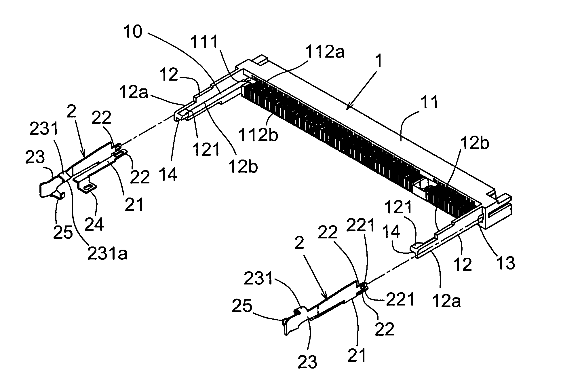
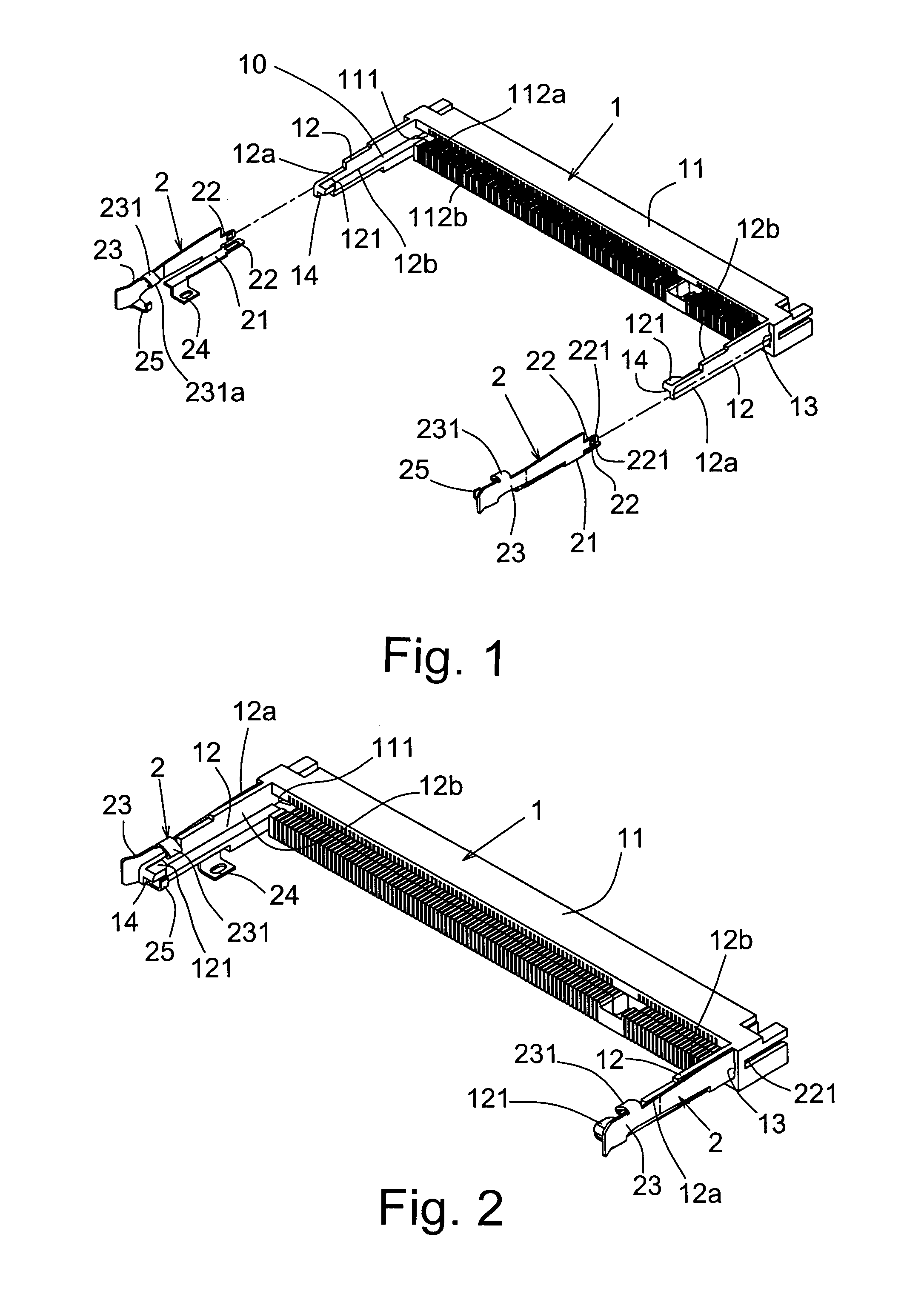
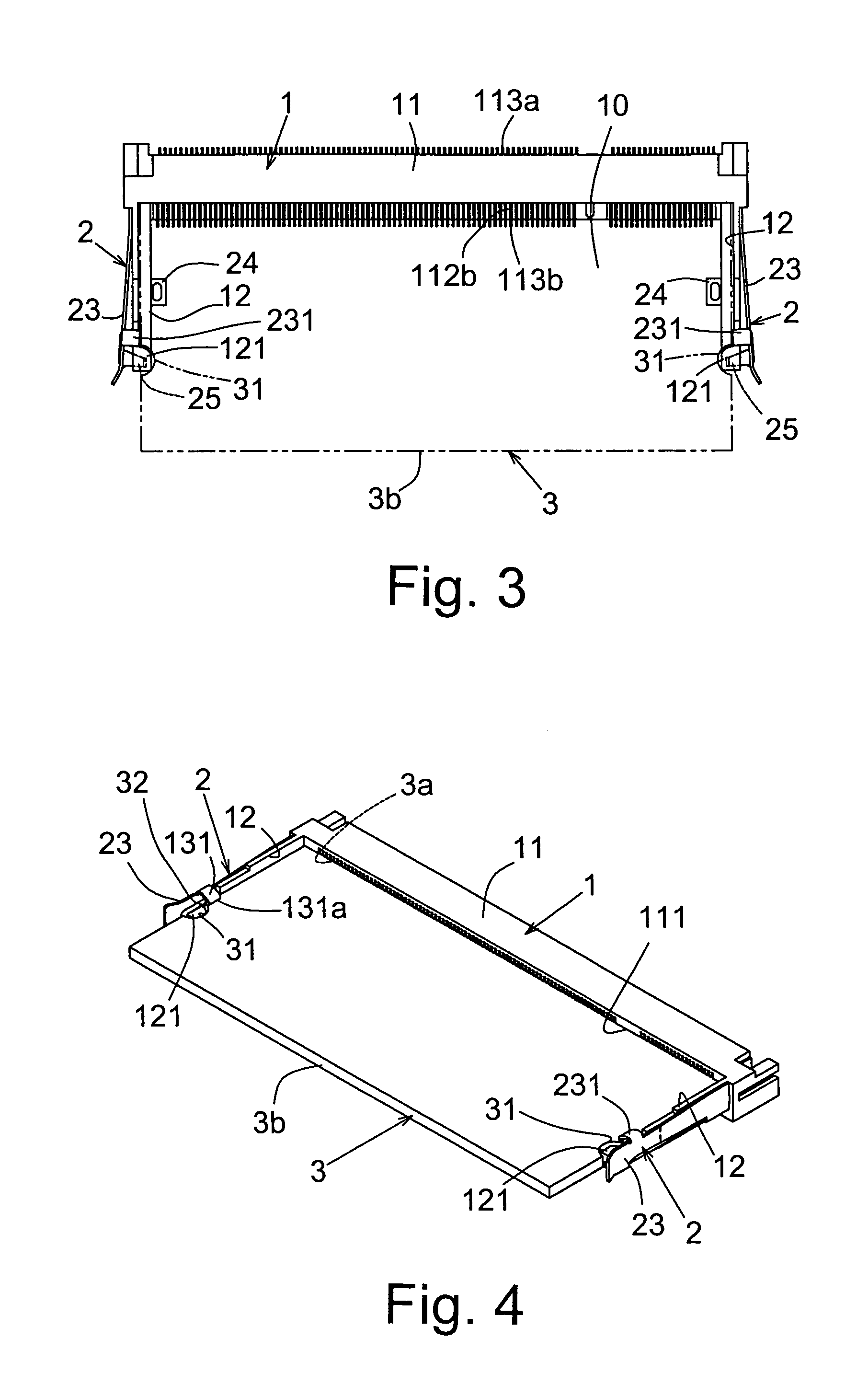
[0022]Please refer to FIGS. 1 to 5. The present invention includes: a plastic main body 1 in which multiple terminals are inlaid, at least one lateral arm 12 projecting from each side of the main body 1, the two lateral arms 12 defining therebetween an electronic card receptacle 10, a stopper block 121 being formed on each lateral arm 12; and at least two resilient members 2 respectively fitted on outer sides 12a of the lateral arms 12. Each resilient member 2 has a bent stopper board section 231 projecting from the resilient member 2. The stopper board section 231 projectively extends to the inner side 12b of the lateral arm 12 and is positioned above the electronic card receptacle 10. When a user places in an electronic card 3 from upper side to lower side, the electronic card 3 first outward resiliently stretches the resilient members 2 and then the stopper blocks 121 of the lateral arms 12 are correspondingly engaged in two locating dents 31 formed on two sides of the electronic...


PUM


Abstract

An electronic card connector with fixed lateral arms, including: a plastic main body in which multiple terminals are inlaid, at least one lateral arm projecting from each side of the main body, the two lateral arms defining therebetween an electronic card receptacle, a stopper block being formed on each lateral arm; and at least two resilient members respectively fitted on outer sides of the lateral arms. Each resilient member has a bent stopper board section projecting from the resilient member. The stopper board section projectively extends to the inner side of the lateral arm and is positioned above the electronic card receptacle.

Description

BACKGROUND OF THE INVENTION[0001]1. Field of the Invention[0002]The present invention is related to an electronic card connector with fixed lateral arms. During the procedure of insertion or taking out of the electronic card, it is unnecessary to outward bias the lateral arms on two sides of the plastic main body. Therefore, the lateral arms are protected from being broken or damaged. Accordingly, the using life of the electronic card connector can be prolonged.[0003]2. Description of the Prior Art[0004]FIG. 10 shows a connector applied to a conventional electronic card. The connector includes a plastic main body 91. Multiple terminals 911 are side by side inlaid in the base section of the main body 91 for electrically connecting with an inserted electronic card. Two lateral arms 912 respectively extend from two sides of the main body 91. The connector further includes two fixing resilient plates 92. Each fixing resilient plate 92 has an insertion plate 921 inserted in the main body...

Claims


Application Information

Patent Timeline
Patent Type & Authority Patents(United States)
IPC IPC(8): H01R13/62H05K7/14
CPCH05K7/1431
Inventor LEE, IPSON
Owner SUPER LINK ELECTRONICS
Why Eureka
Try Eureka