Commutator assembly for motor

a technology of commutator and motor, which is applied in the direction of current collector, dynamo-electric machines, and connections effected by permanent deformation, etc., can solve the problems of coil b>6/b>/i>a /i>a /i>a /i>a /i>a /i>a /i>a /i>a /i>a /

Inactive Publication Date: 2005-09-27
MITSUBISHI ELECTRIC CORP
View PDF12 Cites 3 Cited by
  • Summary
  • Abstract
  • Description
  • Claims
  • Application Information

AI Technical Summary

Benefits of technology

[0015]An object of the present invention, which was made to solve the above problems, is to provide a commutator assembly in which the reliability of electric contact of conductive wires and commutator segments is secured as well as the reliability of mechanical strength of the conductive wires is secured.

Problems solved by technology

Thus, the reliability of mechanical strength of the coil 6a is lowered by the excessive deformation thereof, whereby the coil 6a is liable to be broken.
Furthermore, while the rates of deformation of the coils 6a, 6b, and 6c are controlled by an amount of crush of the hook 10, there is also a problem that it is difficult to control the rates of deformation of them because the amount of crush is dispersed.

Method used


Image

  • Commutator assembly for motor
  • Commutator assembly for motor
  • Commutator assembly for motor

Examples


embodiment 1

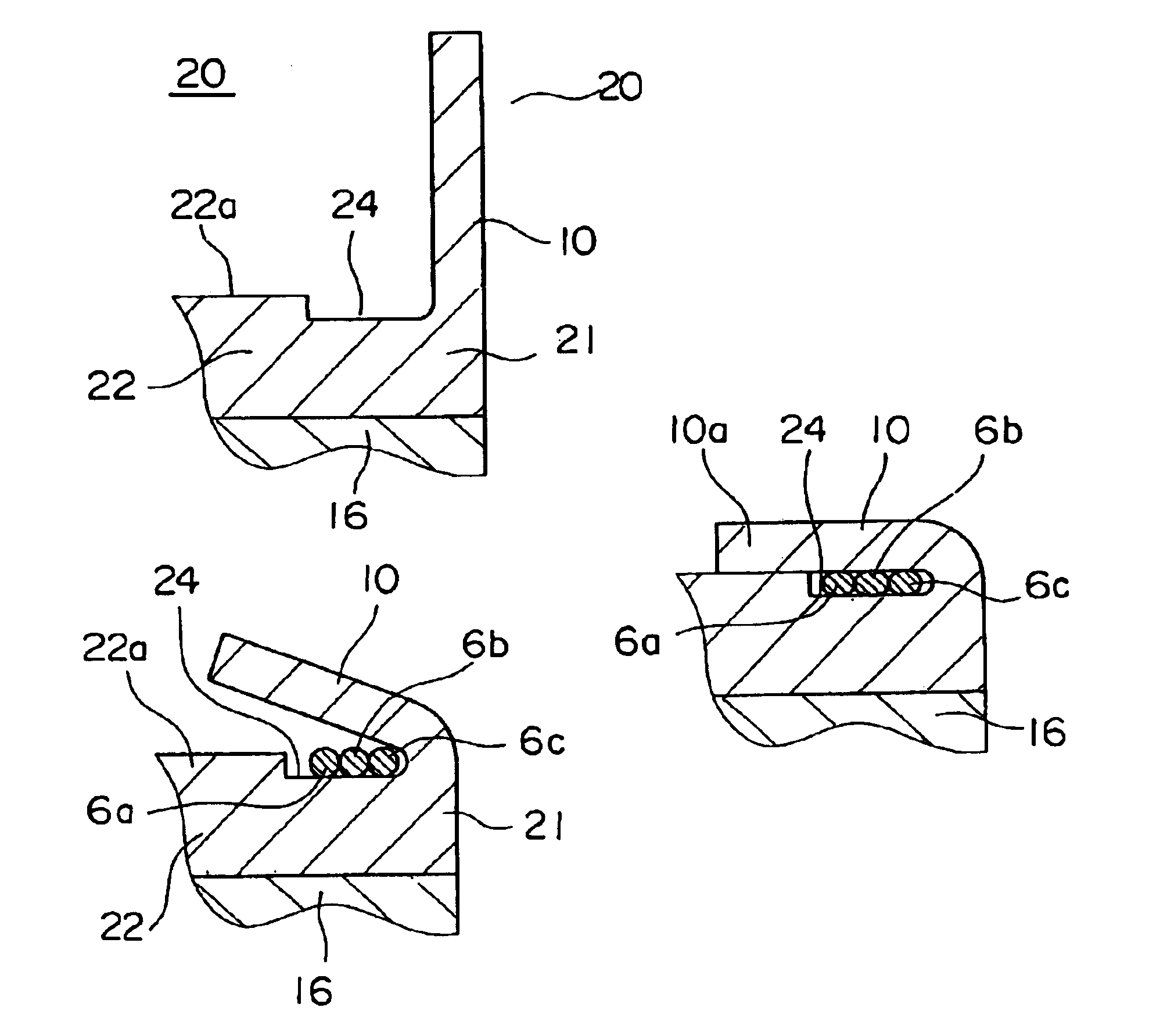
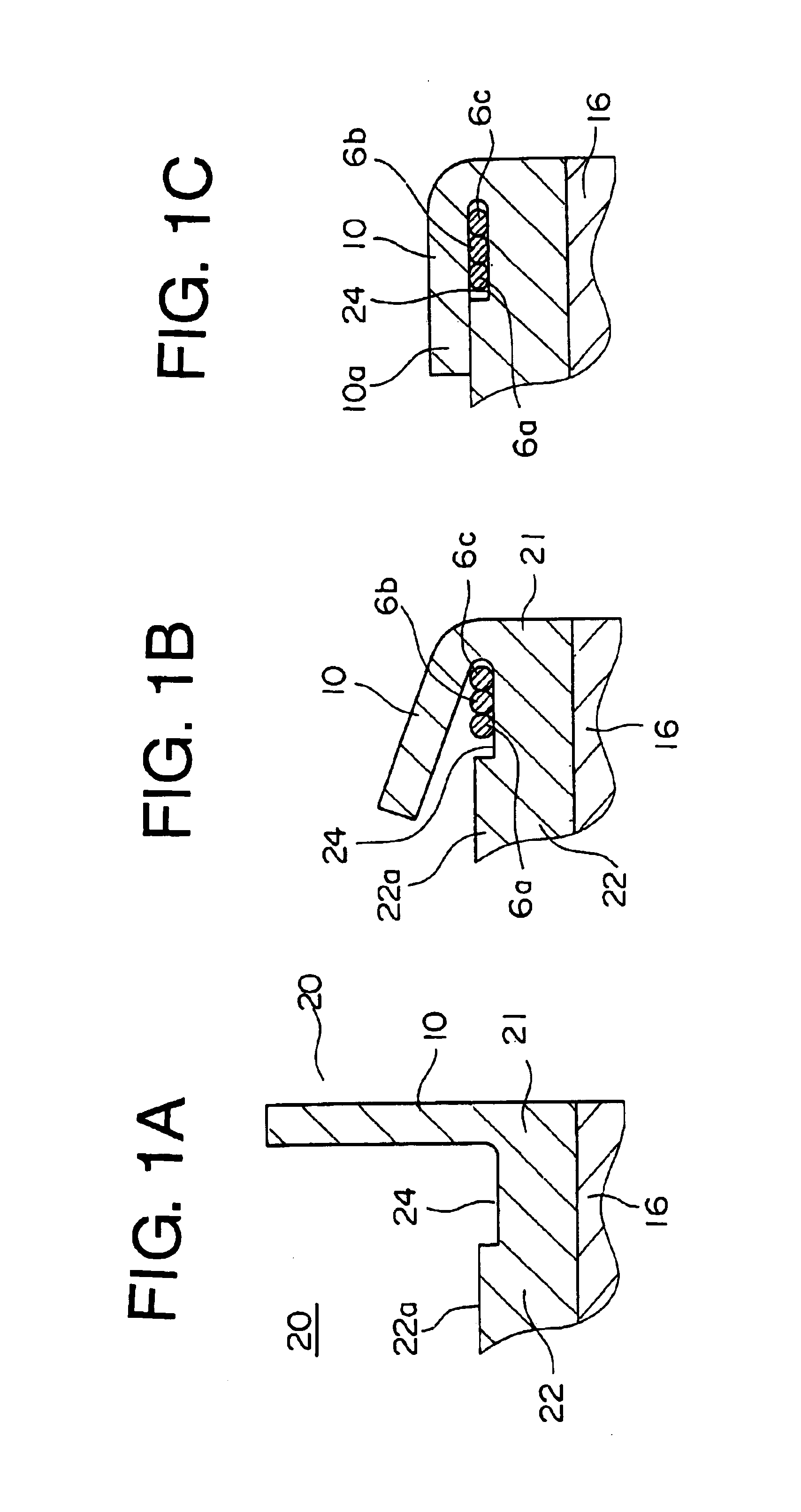
[0045]FIGS. 1A to 1C are sectional view of a main portion of a commutator assembly 20 of a first embodiment of the present invention. The commutator assembly 20 is composed of a commutator 21 and four brushes which are placed at equal intervals and caused to come into contact with the surface of the commutator 21 by the elastic force of springs. The commutator 21 is secured to an end of a shaft 1 and composed of commutator segments 22 as many as a plurality of slots disposed on the shaft 1 in the peripheral direction thereof and a base 16 for supporting the commutator segments 7. Further, a recessed portion 24 is formed on the peripheral surface 22a, which is located on the hook 10 side, of each of the commutator segments 22 which are in contact with the brushes to accommodate the coils 6a, 6b, and6c of an armature 2.

[0046]In the commutator assembly 20, since the coils 6a, 6b, and 6c are accommodated in the recessed portion 24, the coil 6a at the extreme end of the hook 10 and the c...

embodiment 2

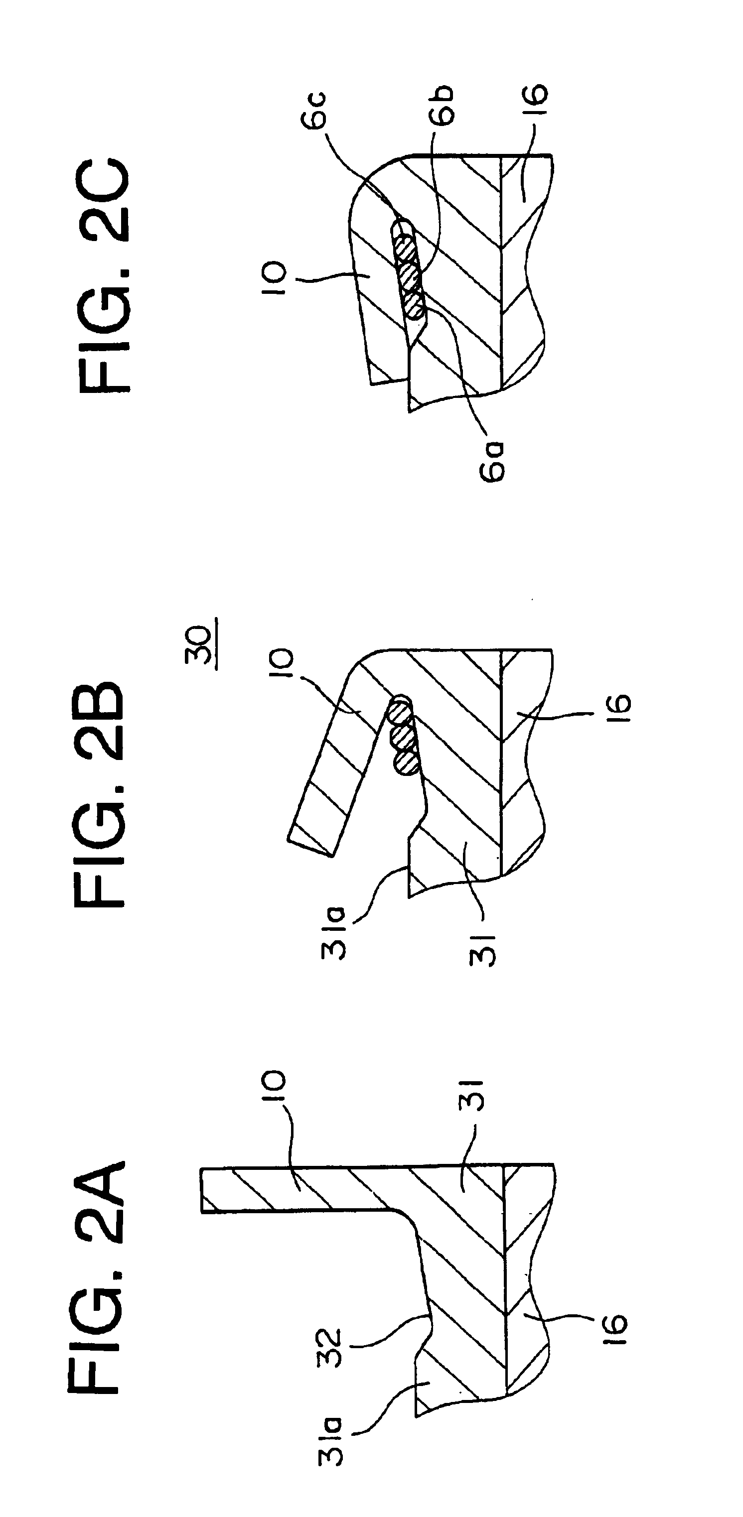
[0050]FIGS. 2A to 2C are sectional views of a main portion of a commutator assembly 30 of a second embodiment of the present invention. While the commutator assembly 30 is similar to that of the embodiment 1 in that a recessed portion 32 is formed on a commutator segment 31 on a hook 10 side, it is different from the embodiment 1 in that the bottom of the recessed portion 32 inclines so as to increase its depth from the root of the hook 10 toward a direction opposite to an armature 2.

[0051]In general, when the hook 10 is bent, it is deformed with a certain radius of curvature at the root thereof and occupies a relatively large cavity at the root thereof than at the extreme end thereof after it is bent.

[0052]In the embodiment 2, after the hook 10 is bent, the cavity in the recessed portion 32 has the same size in the portion where the coil 6a is accommodated on the side thereof opposite to the armature 2 and in the portion where the coil 6c is accommodated on the armature 2 side ther...

embodiment 3

[0054]FIGS. 3A to 3C are sectional views of a main portion of a commutator assembly 35 of an embodiment 3 of the present invention. The commutator assembly 35 is different from that of the embodiment 1 in that a stepped portion 38 is disposed adjacent to a recessed portion 37 formed to a commutator segment 36 and an equalizer 9 is placed on the stepped portion 38. The stepped portion 38 acts as a press and deformation promoting unit for promoting the press and deformation of the equalizer 9. The equalizer 9 is composed of a brass wire covered with an insulation film and having a wire diameter smaller than that of coils 6a, 6b, and 6c. The equalizer 9 may be composed of a red brass wire covered with an insulation film.

[0055]When the wire diameter of the equalizer 9 located at the root of the hook 10 is smaller than that of the coils 6, there is a possibility that the rate of deformation of the equalizer 9 is smaller that of the coils. However, the rate of deformation of the equalizer...


PUM


Abstract

A commutator assembly for a motor has a recessed portion formed to each commutator segment so that coils, which are pressed and deformed by bending the hooks of commutator segments, can be accommodated in the recessed portion. With this arrangement, the commutator assembly can improve the reliability of electric connection of the hook of the commutator segments with a conductive wire.

Description

BACKGROUND OF THE INVENTION[0001]1. Field of the Invention[0002]The present invention relates to a commutator assembly for a motor in which conductive wires are electrically connected to a hook formed on one side of a commutator segment of a commutator.[0003]2. Description of the Related Art[0004]FIG. 13 is a front sectional view of a main portion of a conventional motor, FIGS. 14 to 16 are enlarged views of a main portion of a commutator assembly and show respective steps until coils are locked to hooks.[0005]The motor includes a cylindrical yoke, a permanent magnet composed of four ferrites secured in the yoke in a peripheral direction at intervals, a shaft 1 disposed in the yoke through bearings so as to be rotate freely, an armature 2 secured to the shaft 1, and a commutator assembly 3 disposed on one side of the armature 2. Note that the yoke and the permanent magnet are not illustrated.[0006]The armature 2 is composed of an iron core 4 and a winding 5. The iron core 4 has a pl...

Claims


Application Information

Patent Timeline
Patent Type & Authority Patents(United States)
IPC IPC(8): H01R39/00H02K13/04H01R39/32H01R4/16H02K3/02H02K23/00
CPCH01R39/32H02K13/04
Inventor NAKAYAMA, EIJIYAMAMOTO, MASAYOSHIOHATA, KATSUMIOKADA, KEIGO
Owner MITSUBISHI ELECTRIC CORP
Why Eureka
Try Eureka