Movable contact for a push-on switch, and push-on switch

a technology of movable contact and push-on switch, which is applied in the direction of movable contact, contact surface shape/structure, snap-action arrangement, etc., can solve the problems of inability to achieve a long life period of the center plate portion, insufficient sense, and flat mounting surface, etc., to achieve excellent sense, reduce the width of the movable contact, and reduce the size in the width direction

Active Publication Date: 2005-10-04
HOSIDEN CORP
View PDF10 Cites 21 Cited by
  • Summary
  • Abstract
  • Description
  • Claims
  • Application Information

AI Technical Summary

Benefits of technology

[0011]In the movable contact for a push-on switch of the invention, the peripheral plate portion is formed into a rectangular annular shape, and hence the width of the movable contact can be decreased. In succession to a first-step operation in which the pair of connecting plate portions are inverted to a downward inclined state with providing a sense to make contact with the first stationary contacts which are in the same plane as the support surface of the rectangular annular peripheral plate portion, conducted is a second-step operation in which the center part of the center plate portion is inverted to a downward inflated state with providing a sense with using the pair of connecting plate portions as fulcrums to make contact with a second stationary contact which is in the same plane as the support surface of the rectangular annular peripheral plate portion. Even on al flat stationary-contact forming surface of a printed circuit board, a flexible printed circuit board, or the like, therefore, each of the first- and second-step operations can be conducted with producing an excellent sense. Since the center plate portion which functions in the second-step operation is formed into an oval shape, the size in the width direction can be decreased while realizing a long life period (high durability). Therefore, the movable contact for a push-on switch of the invention attains a beneficial advantage that, even on a flat stationary-contact forming surface of a printed circuit board, a flexible printed circuit board, or the like, an excellent sense and a long life period can be obtained while decreasing the width.
[0012]In the push-on switch of the invention, the movable contact for a push-on switch of the invention is disposed on the flat upper face of a printed circuit board or a flexible printed circuit board, or on the bottom face of the rectangular recess which is formed in the upper face of a printed circuit board or a flexible printed circuit board, and in which the depth is smaller than the height of the movable contact for a push-on switch of the invention, and the movable contact is fixed by the adhesive tape which is bonded from the side of the upper face. Therefore, the invention attains beneficial advantages that it is possible to provide a two-step push-on switch which has a simple structure, which is economical and very thin, and which can realize an excellent sense and a long life period while decreasing the width, even on a flat stationary-contact forming surface of a printed circuit board, a flexible printed circuit board, or the like, and that it is possible to provide a two-step push-on switch which can be configured even on a side face of a thin electronic apparatus.

Problems solved by technology

Therefore, there arises a problem in that a sufficient sense is hardly obtained in a case of a flat mounting surface such as the case of a printed circuit board (PCB) or a flexible printed circuit board (FPC).
By contrast, when the whole diameter is reduced, the width can be decreased, but a long life period of the center plate portion cannot be attained.

Method used


Image

  • Movable contact for a push-on switch, and push-on switch
  • Movable contact for a push-on switch, and push-on switch
  • Movable contact for a push-on switch, and push-on switch

Examples


Embodiment Construction

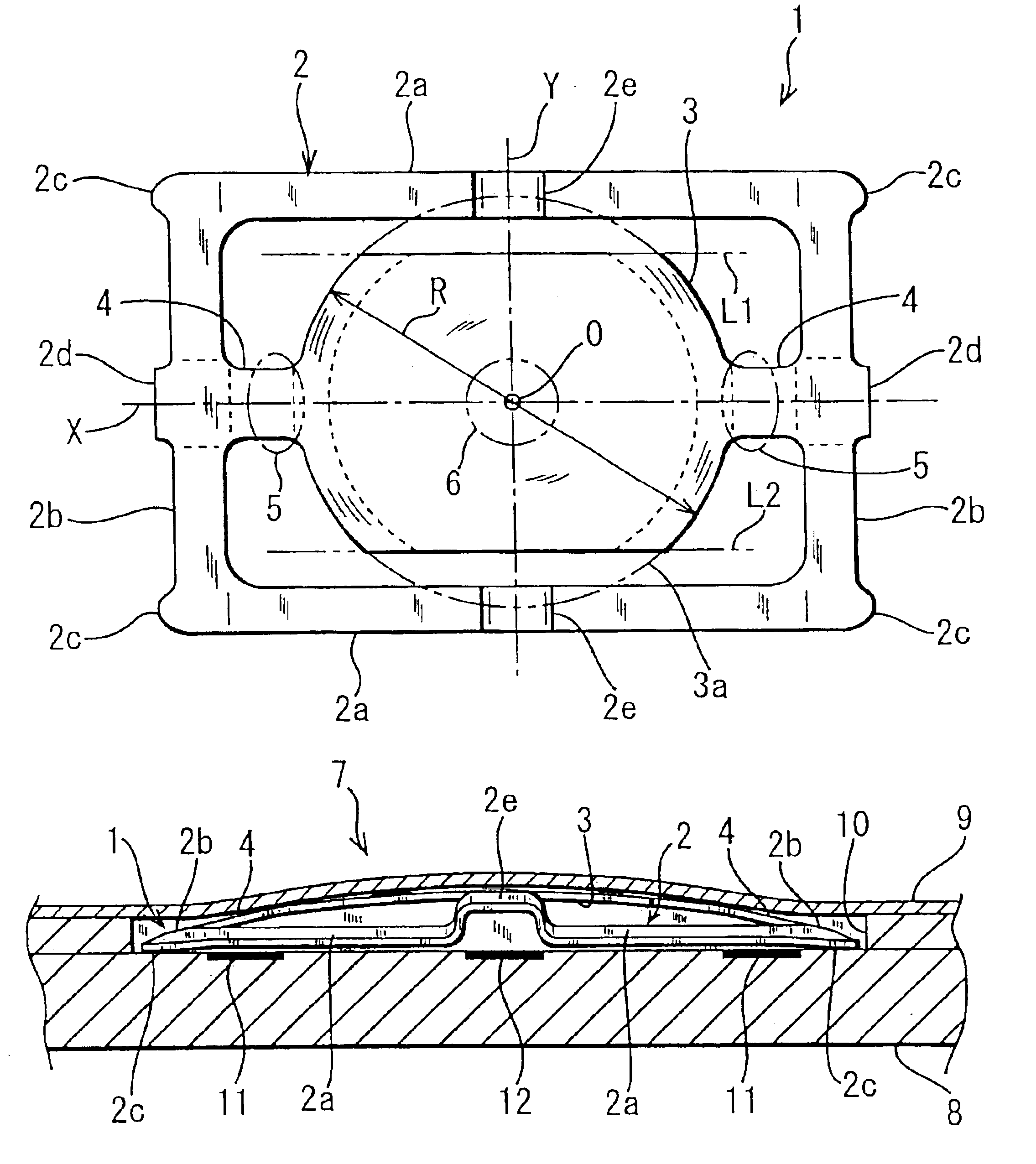
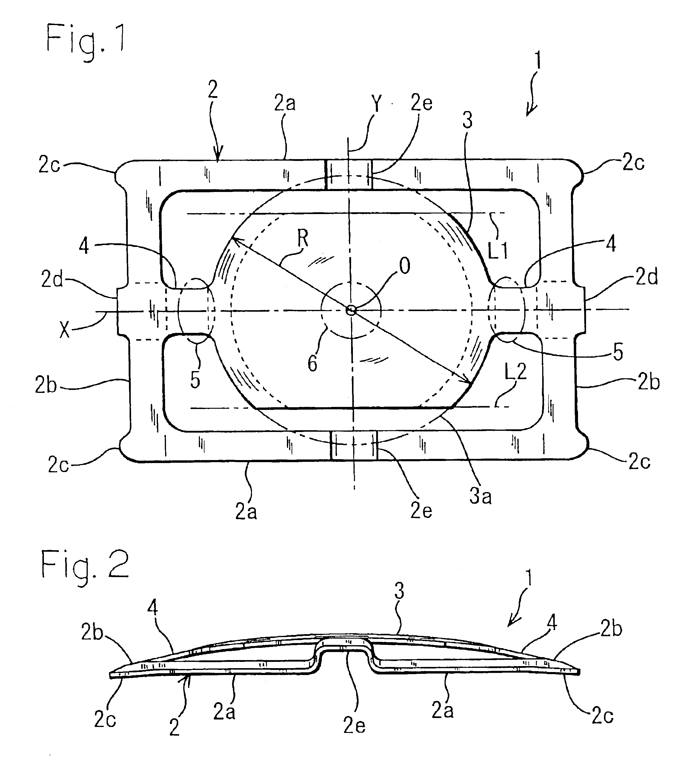
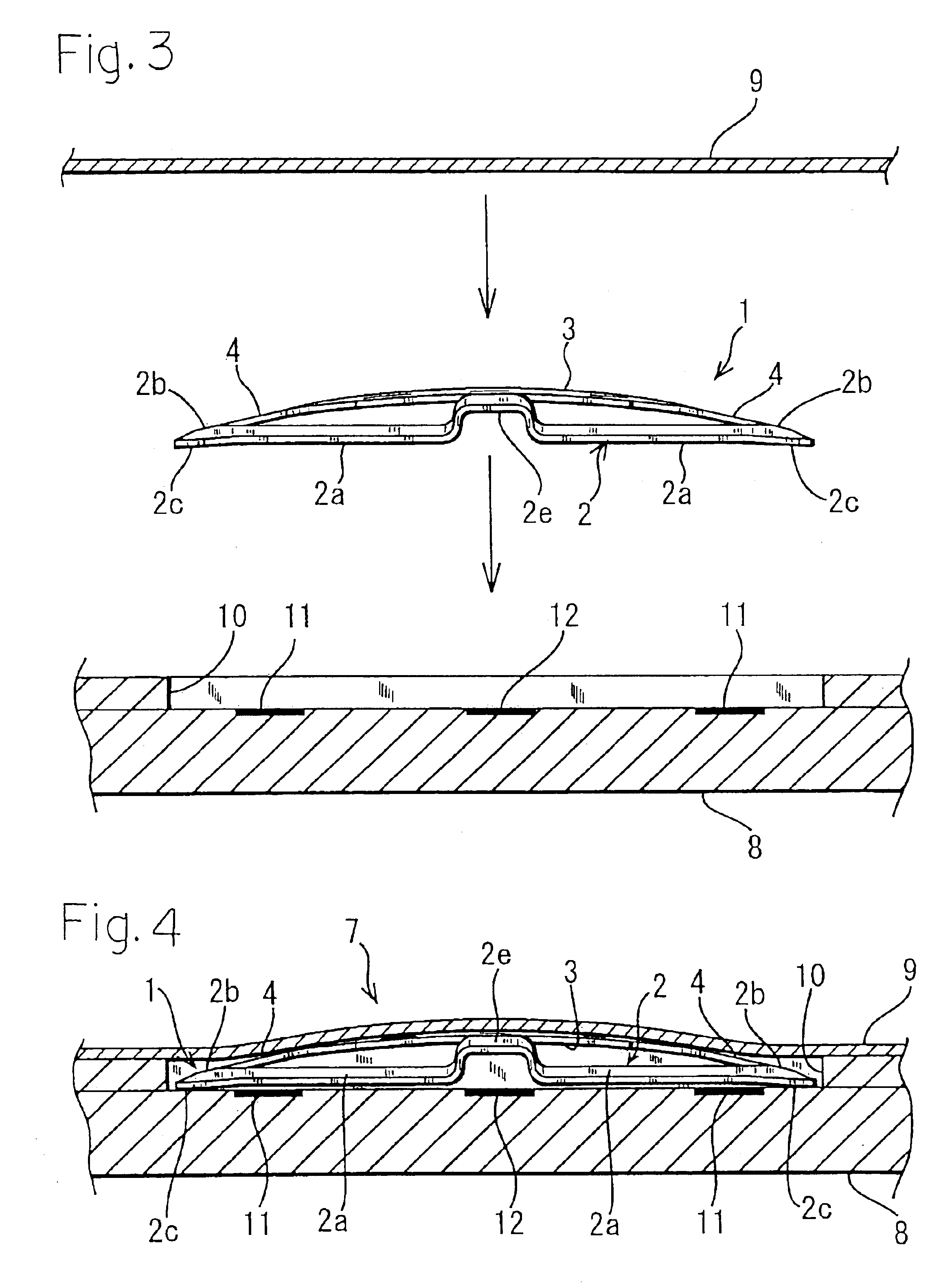
[0018]Hereinafter, en embodiment of the invention will be described with reference to the accompanying drawings. FIGS. 1 and 2 show a movable contact of the embodiment. The movable contact 1 is formed by conducting a pressing process on one thin elastic metal plate (a thin plate spring member made of a metal), and has: an annular peripheral plate portion 2; a center plate portion 3 which is upward inflatingly curved; and a pair of narrow-width connecting plate portions 4, 4 which connect these plate portions together. The peripheral plate portion 2 is formed into a rectangular annular frame-like shape. In the peripheral plate portion 2, a pair of long side portions 2a, 2a and a pair of short side portions 2b, 2b, i.e., the whole periphery of the peripheral plate portion 2 is upward inclined as advancing from the outer side edge toward the inner side edge. Outer side edges of the end portions and middle portion of the short side portions 2b, 2b are partially protruded in an obliquely...


PUM


Abstract

The invention provides a movable contact for a two-step push-on switch which can realize an excellent sense and a long life period while decreasing the width, even on a flat stationary-contact forming surface of a printed circuit board, a flexible printed circuit board or the like, and also a two-step push-on switch.A movable contact has: a rectangular annular peripheral plate portion 2; an oval center plate portion 3 which is upward inflatingly curved; and a pair of connecting plate portions 4, 4 which connect an inner edge of the peripheral plate portion 2 to an outer edge of said center plate portion 3 on a center line X which is parallel to long side portions 2a, 2a of said peripheral plate portion 2. The movable contact is disposed on a flat stationary-contact forming surface of a printed circuit board, a flexible printed circuit board, or the like, and an adhesive tape 9 for fixing the movable contact is bonded from a side of the upper face, thereby configuring a push-on switch.

Description

BACKGROUND OF THE INVENTION[0001]1. Field of the Invention[0002]The present invention relates to a movable contact for a two-step push-on switch in which first and second switches are sequentially turned ON as a result of a depressing operation, and also to such a push-on switch.[0003]2. Description of the Prior Art[0004]Among two-step push-on switches of this kind, a switch in which first and second movable contacts that are invertable are vertically arranged in two stages (for example, see “Japanese Utility Model Application Laying-Open No. 3-8827”) is improved into a switch in which a single movable contact placed in a case is provided with first and second movable contact portions (for example, see “Japanese Patent Application Laying-Open No. 3-89421”“Japanese Utility Model Publication No. 7-53234” and “Japanese Patent Application Laying-Open No. 11-232962”), whereby the number of parts is reduced, the number of man-hours is reduced, and the switch is thinned.[0005]In the improv...

Claims


Application Information

Patent Timeline
Patent Type & Authority Patents(United States)
IPC IPC(8): H01H13/50H01H13/64H01H13/26H01H13/48H01H5/30H01H13/44H01H13/807
CPCH01H13/48H01H13/64H01H13/807H01H13/44H01H2205/026H01H2215/022H01H2225/01H01H2225/018
Inventor ASADA, MAKOTOKOIZUMI, HIROFUMI
Owner HOSIDEN CORP
Why Eureka
Try Eureka