Method and system for optical proximity correction

a technology of optical proximity and correction method, applied in the field of optical proximity correction method and system, can solve the problems of increasing the number of patterns that cannot be corrected properly, opc fails to solve, and it is difficult to generate precise minute mask patterns on a wafer through optical exposur

Inactive Publication Date: 2005-10-04
KK TOSHIBA
View PDF7 Cites 82 Cited by
  • Summary
  • Abstract
  • Description
  • Claims
  • Application Information

AI Technical Summary

Problems solved by technology

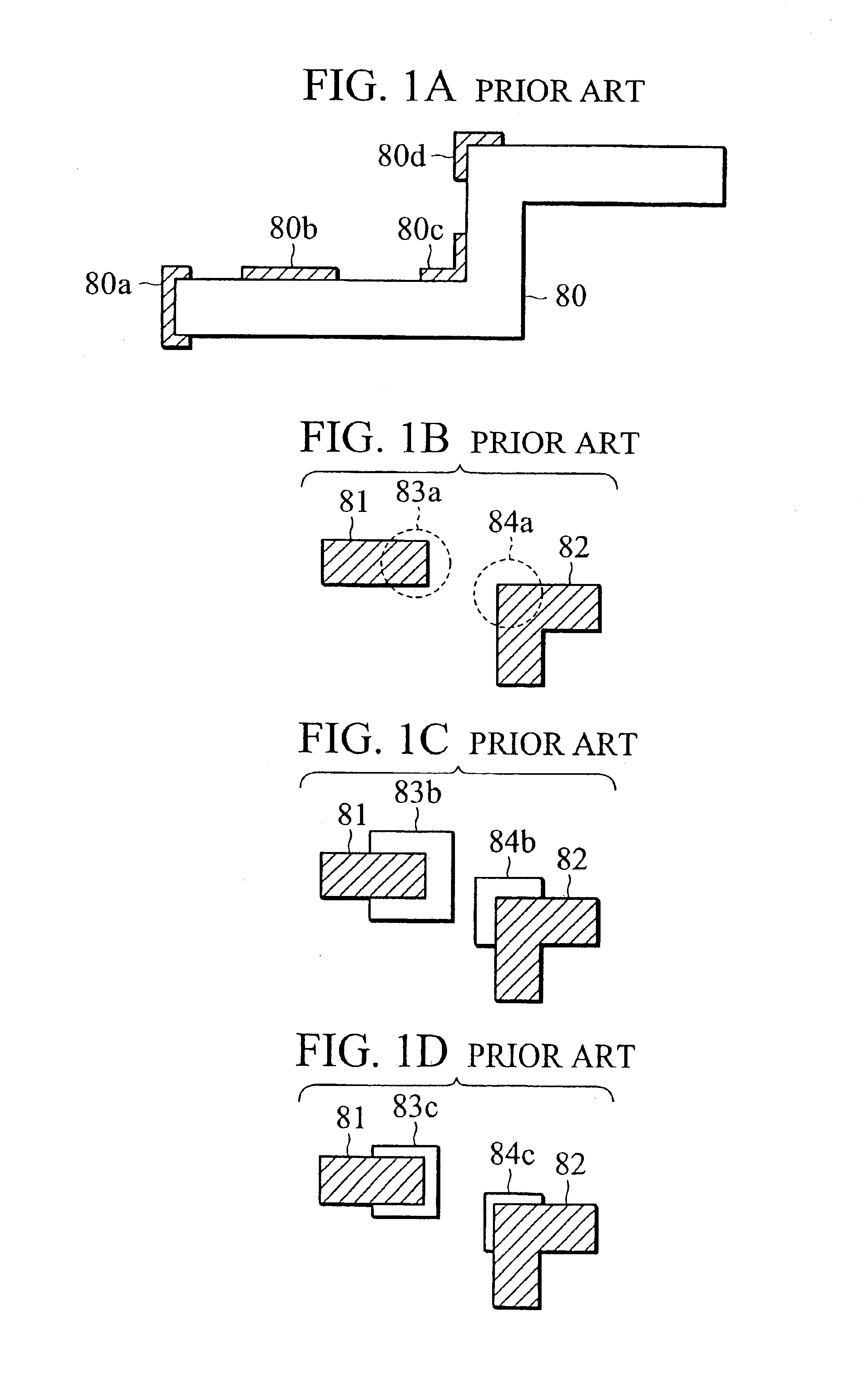
With the miniaturization of semiconductor integrated circuits in recent years, it has become difficult to generate precise minute mask patterns on a wafer through optical exposure.
However, after the process has been conducted for numerous processing generations, an increasing number of patterns cannot be corrected properly, and a more accurate OPC becomes necessary.
Unfortunately, the model-based OPC fails to solve this problem in practice, because it is difficult for the model-based OPC to correct all patterns by a calibration based on actual measurements, in terms of the time necessary for the actual measurement and the enormous amount of data.
In the conventional OPC processing, it takes a lot of time for the lithography simulation to obtain a transferred image, and it also takes a lot of time and many processes to analyze the pattern which is output as a hazardous part and to determine an appropriate corrective treatment, which prolongs the verification time.
In addition, conventionally, each time a nonconformance pattern is discovered in a process or a region, the process must return to the very beginning of the work-flow to correct the OPC setting or the layout design, which also adds time to the overall manufacturing process.
Furthermore, although efforts are made to improve accuracy by adjusting the OPC setting based on the result of the OPC verification, accuracy may be degraded by any side effects on other patterns, which makes the optimization of OPC processing difficult.
In practice, however, it is difficult to apply such specific corrective treatments flexibly to a new pattern variation.
As described, the conventional method fails to complete OPC in a short period of time, and does not conduct appropriate correction on every variation of the patterns.

Method used


Image

  • Method and system for optical proximity correction
  • Method and system for optical proximity correction
  • Method and system for optical proximity correction

Examples


Embodiment Construction

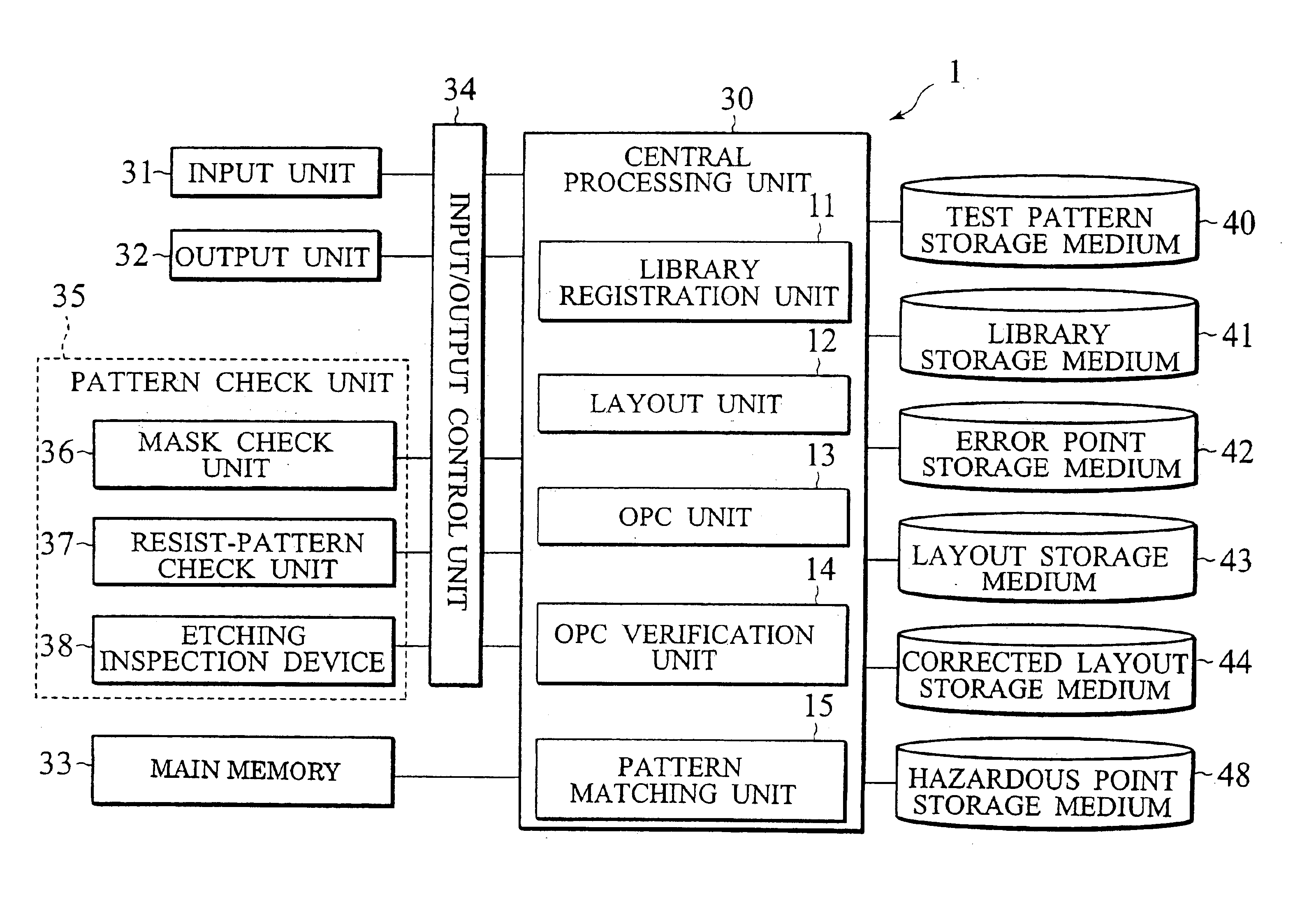
[0053]Various embodiments of the present invention will be described with reference to the accompanying drawings. It is to be noted that the same or similar reference numerals are applied to the same or similar parts and elements throughout the drawings, and the description of the same or similar parts and elements will be omitted or simplified.

[0054]In the following descriptions, numerous specific details are set fourth such as specific signal values, etc. to provide a thorough understanding of the present invention. However, it will be obvious to those skilled in the art that the present invention may be practiced without such specific details in other instances, well-known circuits have been shown in block diagram generate in order not to obscure the present invention in unnecessary detail. In the following description of the embodiments, an optical proximity correction (OPC) system, which can speed up the OPC process to verify the validity of the post-OPC pattern, and an OPC met...


PUM

PropertyMeasurementUnit
densityaaaaaaaaaa
widthaaaaaaaaaa
dimensionaaaaaaaaaa

Abstract

A computer implemented method for OPC includes: storing an improper OPC pattern and a corrective treatment for the improper OPC pattern in a library storage medium; reading a layout pattern; and matching the layout pattern with the improper OPC pattern stored in the library storage medium.

Description

CROSS REFERENCE TO RELATED APPLICATIONS[0001]This application is abased upon and claims the benefit of priority from prior Japanese Patent Application P2001-359956 filed on Nov. 26, 2001; the entire contents of which are incorporated by reference herein.BACKGROUND OF THE INVENTION[0002]1. Field of the Invention[0003]The present invention relates to methods and systems for optical proximity correction (hereinafter referred to as “OPC”) for layout design and verification processing of mask data for semiconductor integrated circuits.[0004]2. Description of the Related Art[0005]With the miniaturization of semiconductor integrated circuits in recent years, it has become difficult to generate precise minute mask patterns on a wafer through optical exposure. As a result, in order to generate minute mask patterns, certain graphics are added on the mask pattern in advance, or OPC is conducted which corrects the dimension of the pattern depending on the density of the pattern. OPC can be grou...

Claims


Application Information

Patent Timeline
Patent Type & Authority Patents(United States)
IPC IPC(8): G03F1/14G03F1/36G03F1/68G03F1/70G06F17/50H01L21/027H01L21/82
CPCG03F1/144G03F1/36
Inventor IKEUCHI, ATSUHIKO
Owner KK TOSHIBA
Why Eureka
Try Eureka