Tile cutter

a technology of cutting tools and tiles, applied in the field of tile cutting tools, can solve problems such as unfavorable structure affecting the working characteristics and efficiency, and achieve the effect of improving work efficiency and working characteristics

Active Publication Date: 2005-10-11
ISHII CHOKOKOGU MFG
View PDF5 Cites 20 Cited by
  • Summary
  • Abstract
  • Description
  • Claims
  • Application Information

AI Technical Summary

Benefits of technology

[0009]Accordingly, it is an object of the present invention to provide an easy-to-use tile cutter.
[0010]It is another object of the present invention to provide a tile cutter in which a series of operations from the formation of a cut in the tile surface by a rotary blade following the placement of the tile in a fixed position on a base stand to the pressing and splitting of the tile by the pressing plates are efficiently and reliably performed merely by operating the operating lever.

Problems solved by technology

Thus, the structure unfavorably affects the working characteristics and efficiency.

Method used


Image

  • Tile cutter
  • Tile cutter
  • Tile cutter

Examples


Embodiment Construction

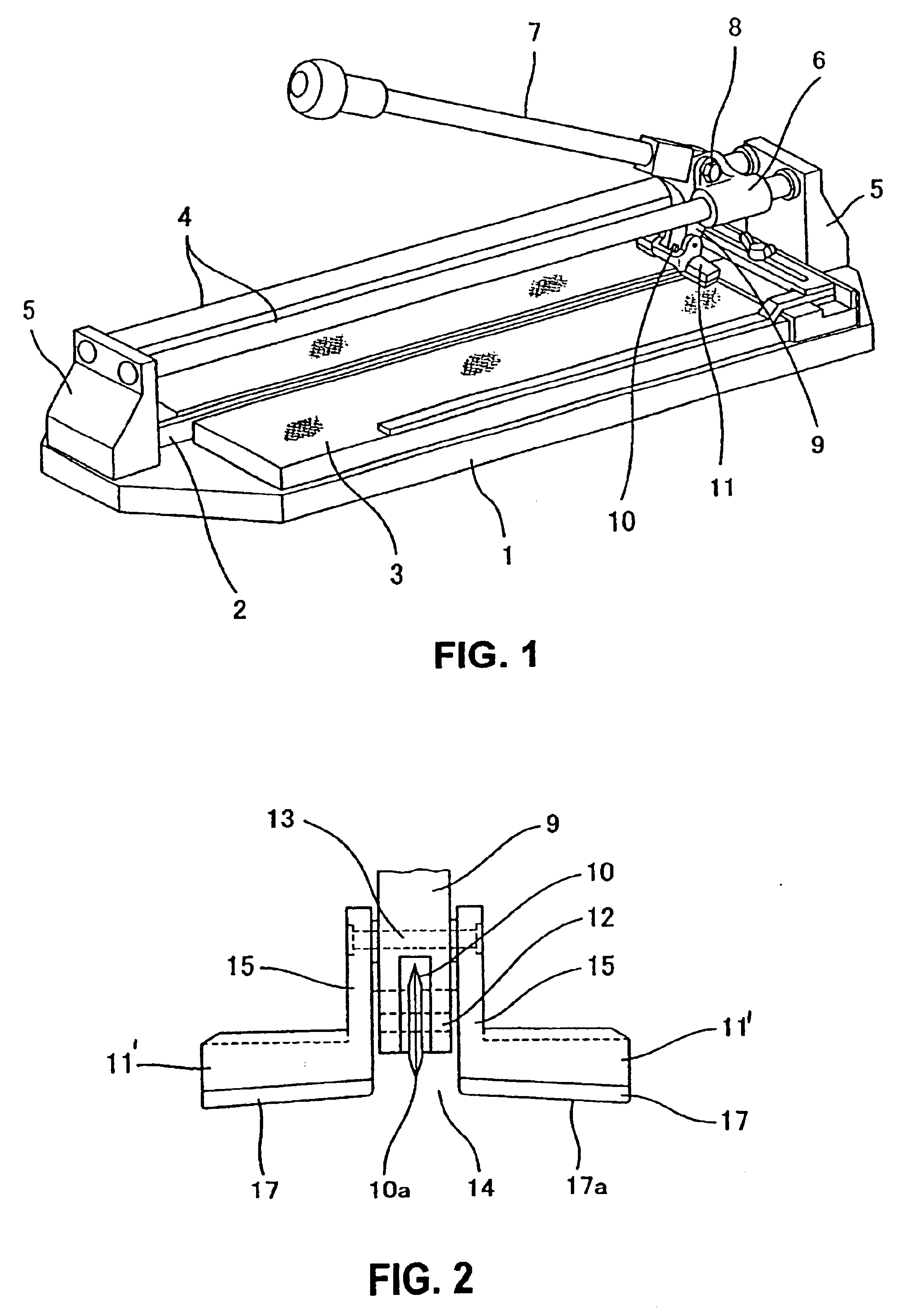
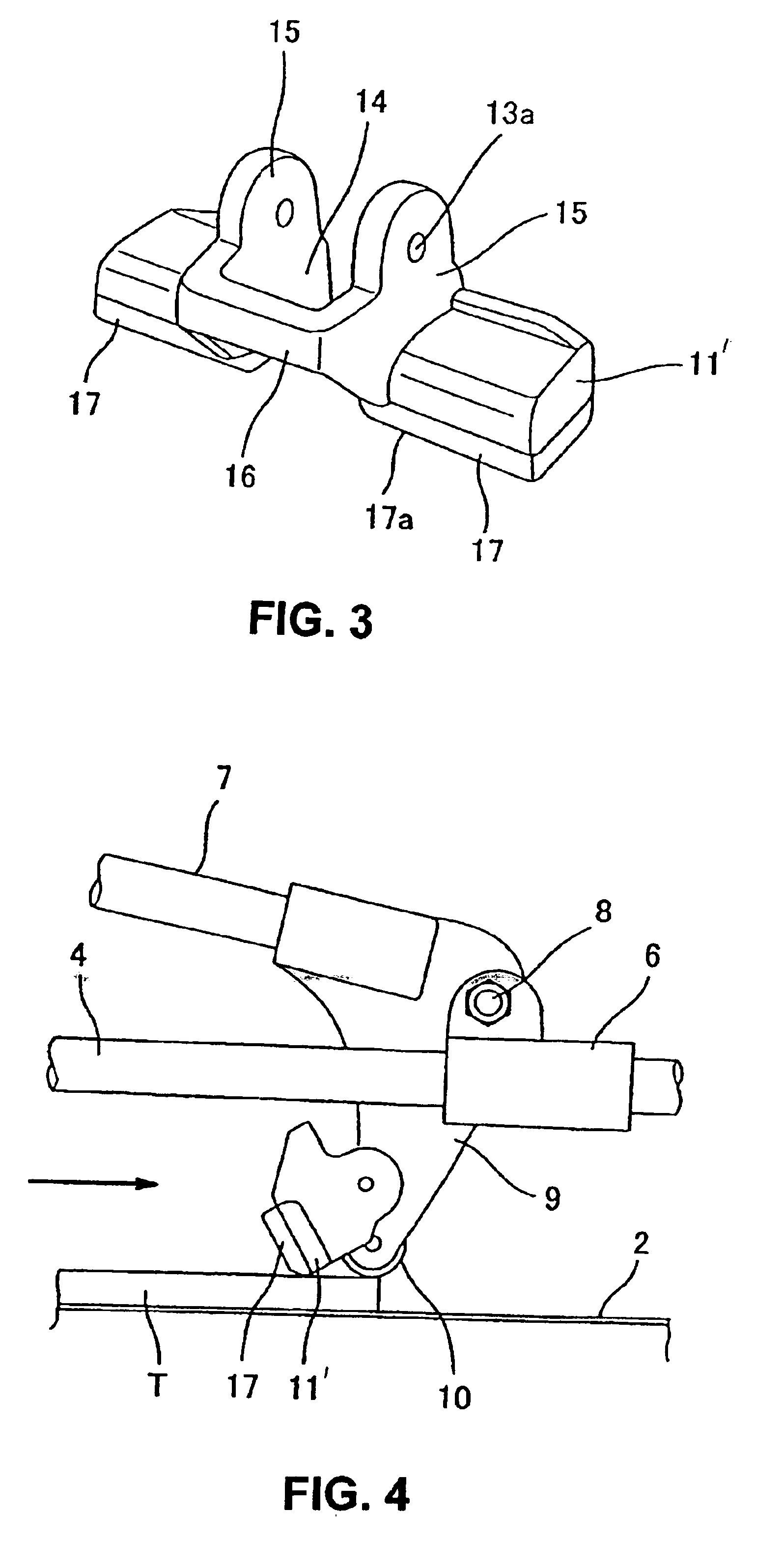
[0031]The tile cutter of the present invention will be described in concrete terms below with reference to the accompanying drawings.

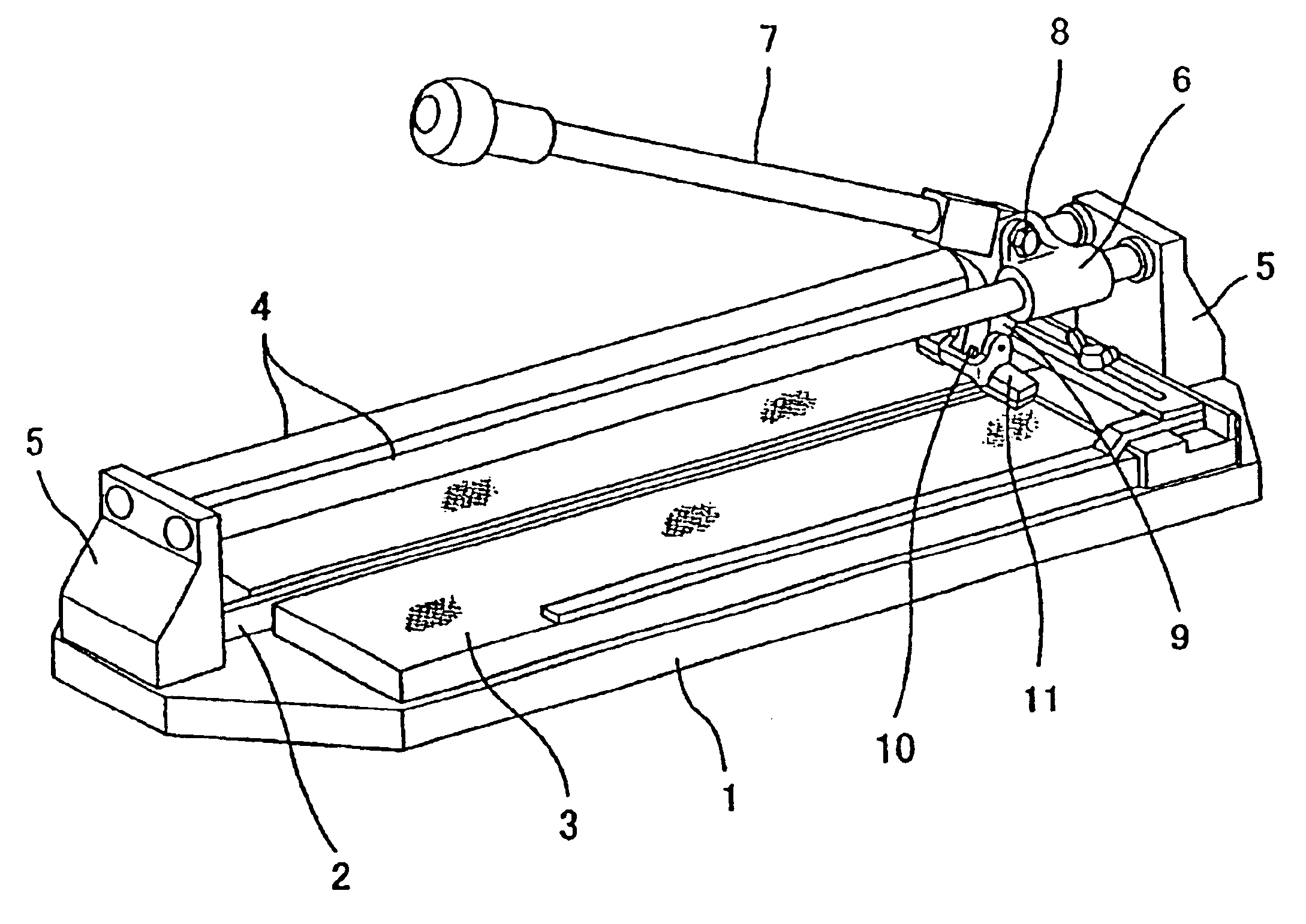
[0032]In FIGS. 1 through 3, the reference numeral 1 indicates a base stand of the tile cutter. The base stand 1 has a substantially rectangular shape when viewed from above, and it has a protruding rib 2 provided in the direction of length of the base stand 1 in the center. Elastic sheets 3 are pasted to the surface of this base stand 1 so that they are on both sides of the protruding rib 2 and are slightly lower in height than the protruding rib 2, thus forming a tile carrying surface.

[0033]Two parallel guide rails 4 are supported by a front supporting stand 5 and by a rear supporting stand 5′ that are installed upright on the front (left side in FIG. 1) end and rear (right side in FIG. 1) end of the base stand 1. The guide rails 4 are disposed above the protruding rib 2 in a bridge-like configuration.

[0034]The reference numeral 6 is a moving base whi...


PUM

PropertyMeasurementUnit
timeaaaaaaaaaa
forceaaaaaaaaaa
thicknessaaaaaaaaaa

Abstract

A tile cutter including a base stand, a protruding rib disposed on the base stand, bridge-like guide rails installed above the protruding rib, an operating lever sliding on the guide rails while being guided by the guide rails, and a rotary blade and a pressing member installed on the base portion of the operating lever, wherein the pressing member is comprised of a pair of pressing plates with a hollow space in between, the pressing plates are connected to each other by a C-shaped connecting element, the pressing member is supported on the base portion of the operating lever near a blade supporting shaft for the rotary blade so that the pressing member is free to swing upward and downward, and part of the base portion of the operating lever and the rotary blade enter the hollow space when the pressing member takes a hanging attitude.

Description

BACKGROUND OF THE INVENTION[0001]1. Field of the Invention[0002]The present invention relates to a tile cutter for cutting ceramic tiles that are to be applied to walls, floors, etc. as construction materials.[0003]2. Prior Art[0004]In one of known tile cutters, a rectilinear protruding rib is disposed on its base stand, guide rails are installed in a bridge-like configuration above the protruding rib, an operating lever is provided on the guide rails so as to move on the guide rails, and a rotary blade and a pressing member are provided at the base portion of this operating lever in front and back positional relationship. This structure is proposed by the inventor of the present application as a tile cutter for cutting tiles to specific dimensions, and it is disclosed in Japanese Utility Model Registration No. 2502324.[0005]In order to cut tiles using this tile cutter, a tile that is to be cut is first placed on the base stand so that a intended cutting line of the tile is aligned ...

Claims


Application Information

Patent Timeline
Patent Type & Authority Patents(United States)
IPC IPC(8): B28D1/22
CPCB28D1/225Y10T225/325B28D1/22
Inventor ISHII, AKINORI
Owner ISHII CHOKOKOGU MFG
Why Eureka
Try Eureka