Jack with modular mounting sleeve

a technology of modular mounting and jack, which is applied in the direction of waveguide devices, coupling device connections, contact members penetrating/cutting insulation/cable strands, etc., and can solve problems such as jacks deflecting

Inactive Publication Date: 2005-10-11
COMMSCOPE TECH LLC
View PDF25 Cites 41 Cited by
  • Summary
  • Abstract
  • Description
  • Claims
  • Application Information

AI Technical Summary

Problems solved by technology

Strain from the cables attached to the jacks may cause the jacks to deflect.

Method used


Image

  • Jack with modular mounting sleeve
  • Jack with modular mounting sleeve
  • Jack with modular mounting sleeve

Examples


Embodiment Construction

[0058]Reference will now be made in detail to exemplary aspects of the present invention which are illustrated in the accompanying drawings. Wherever possible, the same reference numbers will be used throughout the drawings to refer to the same or like parts.

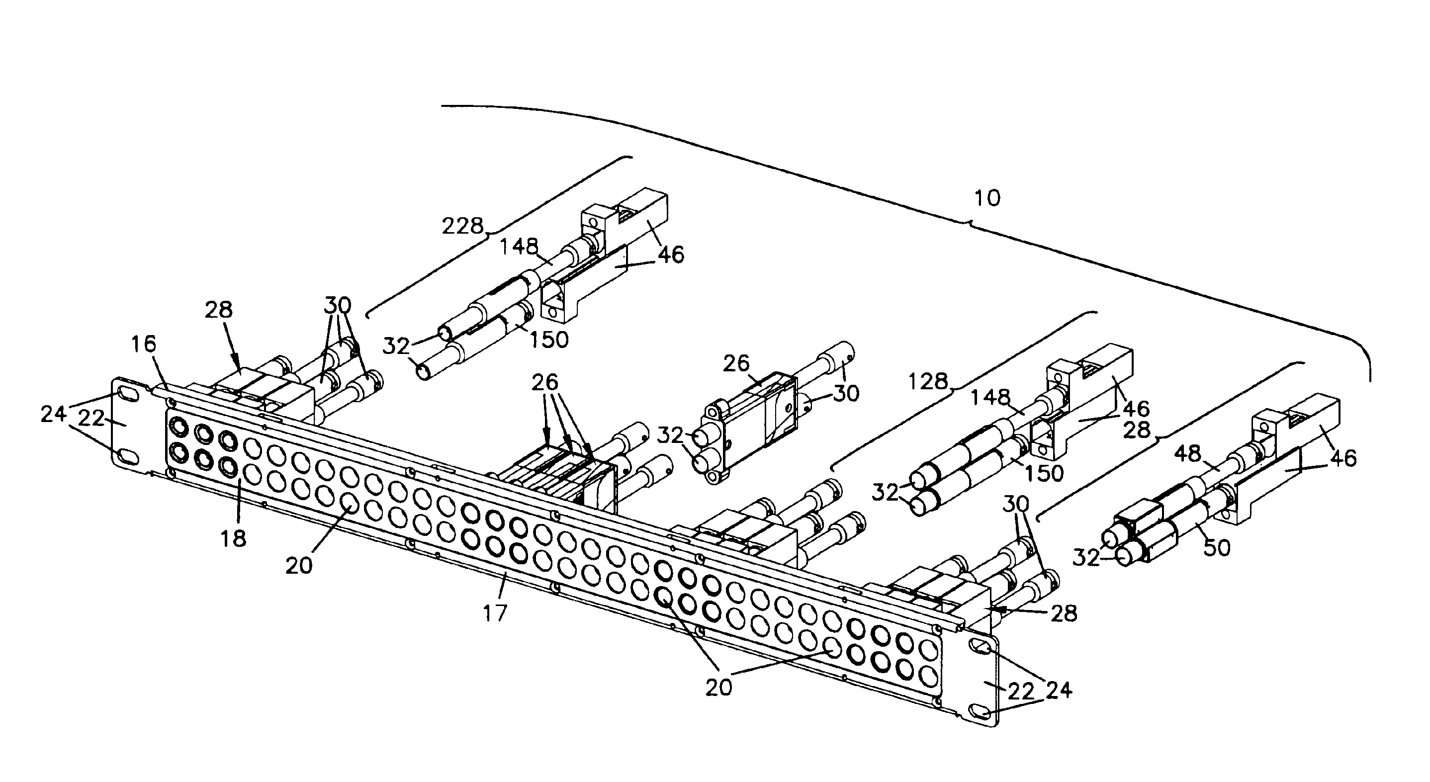
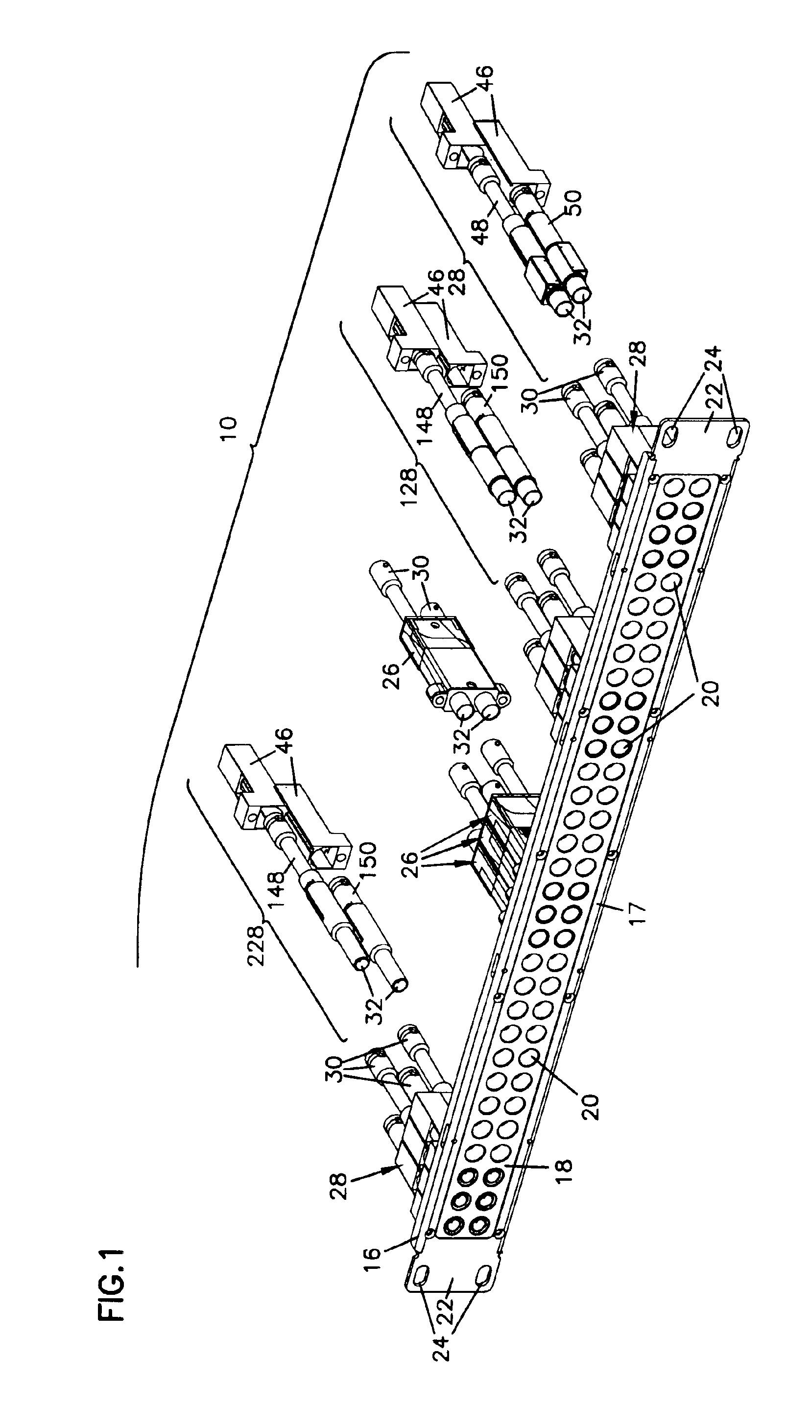
[0059]Patch panels such as a panel 10 in FIG. 1, might be installed in broadcast communications production facilities. Patch panels 10 include a chassis 16 including a mounting frame 17 and a panel front 18 with a plurality of pairs of openings 20. As shown, panel front 18 may be removed from frame 17 to allow different configurations of openings 20 to be included in panel 10. As shown, frame 17 is made of a durable material such as aluminum or steel to provide structural support to chassis 16. Other similar structural materials may be used for frame 17 such as other durable or rigid metals or composite materials. Panel front 18 is molded or formed from plastic or other similar non-conductive material to facilitate the creation ...


PUM


Abstract

A housing for a coaxial jack including an opening for receiving the jack, the opening including a guide for preventing rotation of the jack within the opening. The housing also includes a stop to limit sliding of the jack within the opening and a flange extending from an outer surface. An outer face opposite the flange includes a ridge and a groove. A housing for coaxial jacks includes a pair of openings for receiving jacks. Each opening includes a guide to prevent rotation and a stop to limit sliding of the jack within the opening.

Description

CROSS REFERENCE TO RELATED APPLICATIONS[0001]This application is a continuation of U.S. patent application Ser. No. 10 / 700,366, filed on Nov. 3, 2003 now U.S. Pat. No. 6,848,948.FIELD OF THE INVENTION[0002]The present invention generally relates to mounting connector jacks to facilitate connection of communications circuits.BACKGROUND[0003]In broadcast communications equipment installations, such as in a studio or production facility, it is common to have patch panels to interconnect a variety of signal sources with a variety of downstream processing, recording and broadcast equipment. These patch panels may mount jacks in paired combinations to provide input and output circuits to each piece of equipment. Also, these paired arrangements may include a single jack connected to a monitor circuit mounted adjacent to the jack pairs. Depending on the size and complexity of the installation, these patch panels may have a single paired set of jacks or may include many paired sets in a dens...

Claims


Application Information

Patent Timeline
Patent Type & Authority Patents(United States)
IPC IPC(8): H01R13/428H01R13/00H01R13/514H01R13/646H01R24/58H01P1/04H04Q1/14
CPCH01P1/045H01R13/6585H01R13/514H01R13/719H01R24/46H01R24/52H04Q1/14H04Q1/116H04Q1/023H01R12/7029H01R13/428H01R13/64H01R13/665H01R13/748H01R23/7073H01R2103/00H01R2201/16H04Q2201/10H04Q2201/16H01R13/6471
Inventor KHEMAKHEM, M'HAMED ANISSKLUZACEK, KENNETH ALLEN
Owner COMMSCOPE TECH LLC
Why Eureka
Try Eureka