Automobile jack and wheel dolly

a technology of jack and dolly, which is applied in the field of mechanical devices, can solve the problems of inconvenient use, inconvenient use, and inability to adjust and achieve the effect of convenient adjustment of the length of the base arm

Inactive Publication Date: 2008-05-01
ALLTRADE TOOLS
View PDF58 Cites 38 Cited by
  • Summary
  • Abstract
  • Description
  • Claims
  • Application Information

AI Technical Summary

Benefits of technology

[0010]According to a preferred embodiment of the invention, there is described a wheel dolly suitable for use as an automobile jack capable of holding aloft heavy loads for an extended period of time. In one aspect of the invention, the wheel dolly has two support arms for engaging a wheel, the arms being spaced a horizontal distance from each other. A base arm connects the support arms. The base arm is configured to have its length altered, for which purpose there is provided a first rotatable threaded rod extending axially along the base arm. The first threaded rod is configured to alter the length of the base arm when rotated. One of the ends of the first threaded rod is tipped only by a first nut rotationally fixed that end, the nut being configured to be rotationally driven by a driver. This aspect of the invention provides the dual advantages that the wheel dolly of the present invention is not burdened by arms and levers protruding from its profile, as these may represent hazards while the dolly is being wheeled about a workshop floor. A second advantage is that a user may apply a driver directly to the first nut, thereby easily adjusting the length of the base arm for capturing a wheel in the support arms.

Problems solved by technology

Yet, deficiencies remain in the prior art.
Again, this requires additional space around the dolly in which the user must position himself to operate the device.
In many workshop situations, this activity alongside the dolly may be cramped and inconvenient due to space restrictions, and space may be limited (a common feature of many workshops) to the point that the user may find himself obstructed in activating the dolly, or may knock into other sensitive equipment located nearby.
To the extent the various levers and handles for activating the dolly protrude from the profile of the dolly, wheeling the dolly about a crowded workshop floor is attended by the added danger of bumping into sensitive equipment.
It is well known that hydraulic systems may be suitable for lifting a load, but they are not suitable for holding a load aloft for any length of time once lifted.
This is because hydraulic systems are known to include structure prone to failure, such as O-rings, which may suffer the effects of aging and suddenly give way under load.
Thus, where hydraulic systems are used for lifting, they cannot safely be used to hold heavy loads such as vehicles aloft sufficiently long for an artisan to work underneath the load.
In short, while they may be used as wheel dollies to merely manipulate a wheel, they cannot safely be used alone as automobile support structure for any length of time.
This method of operation has the further disadvantage that the additional mechanical system takes up even more room under the vehicle or load, thus denying a clear access to the artisan.
The prior art also lacks adequate simple and rapidly activatable structure to stabilize a dolly in relation to the floor and prevent it from accidentally moving laterally on its casters.
It will be appreciated that an automobile jack that is not laterally stable would be particularly hazardous in use.
Another problem common in prior art dollies is that they do not possess sufficient degrees of freedom for moving a wheel, in that they cannot be controlled easily to position a wheel or an associated vehicular load within a large range of specific locations, both linear and rotational, when the dolly is in a stationary position.
However, while this pincer action feature is useful for easily positioning a dolly around the base of a wheel, such a dolly does not have much upward travel—being limited to the height of the arms above the floor.
As a result, there may not be enough vertical room under a vehicle lifted in this way to permit an artisan to crawl underneath.
However, such dollies may be difficult to position around the base of a wheel because their lifting arms are commonly fixed a set distance apart, or are difficult to adjust.
The amount thus lifted is lost vertical travel that cannot be imparted to lifting the wheel.
Lost vertical travel may adversely affect the ability of the dolly to accomplish an intended task.
On the other hand, the fixed arms of such a dolly may be too narrow to engage a large wheel, and in this case the dolly may be unusable.

Method used


Image

  • Automobile jack and wheel dolly
  • Automobile jack and wheel dolly
  • Automobile jack and wheel dolly

Examples


Embodiment Construction

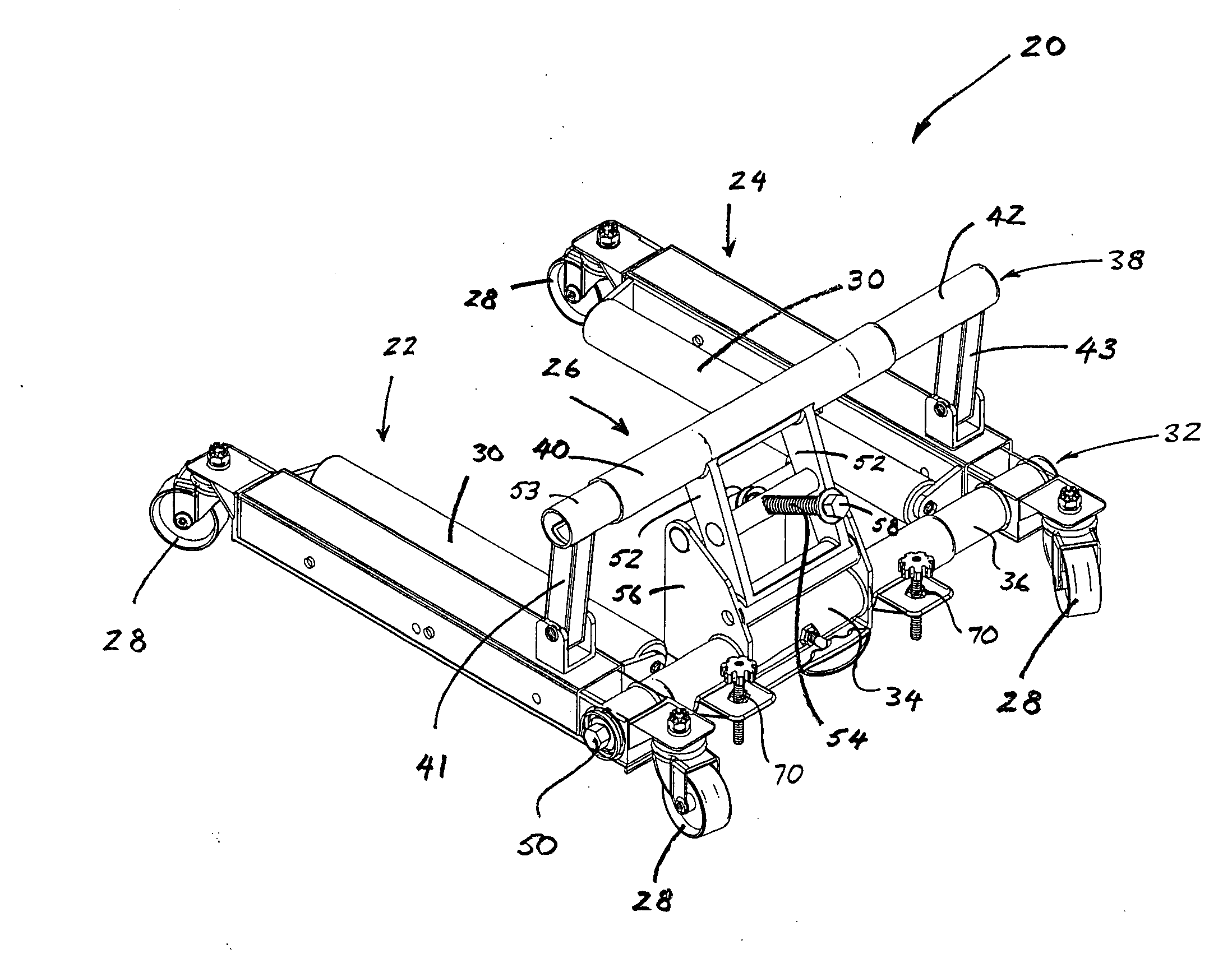
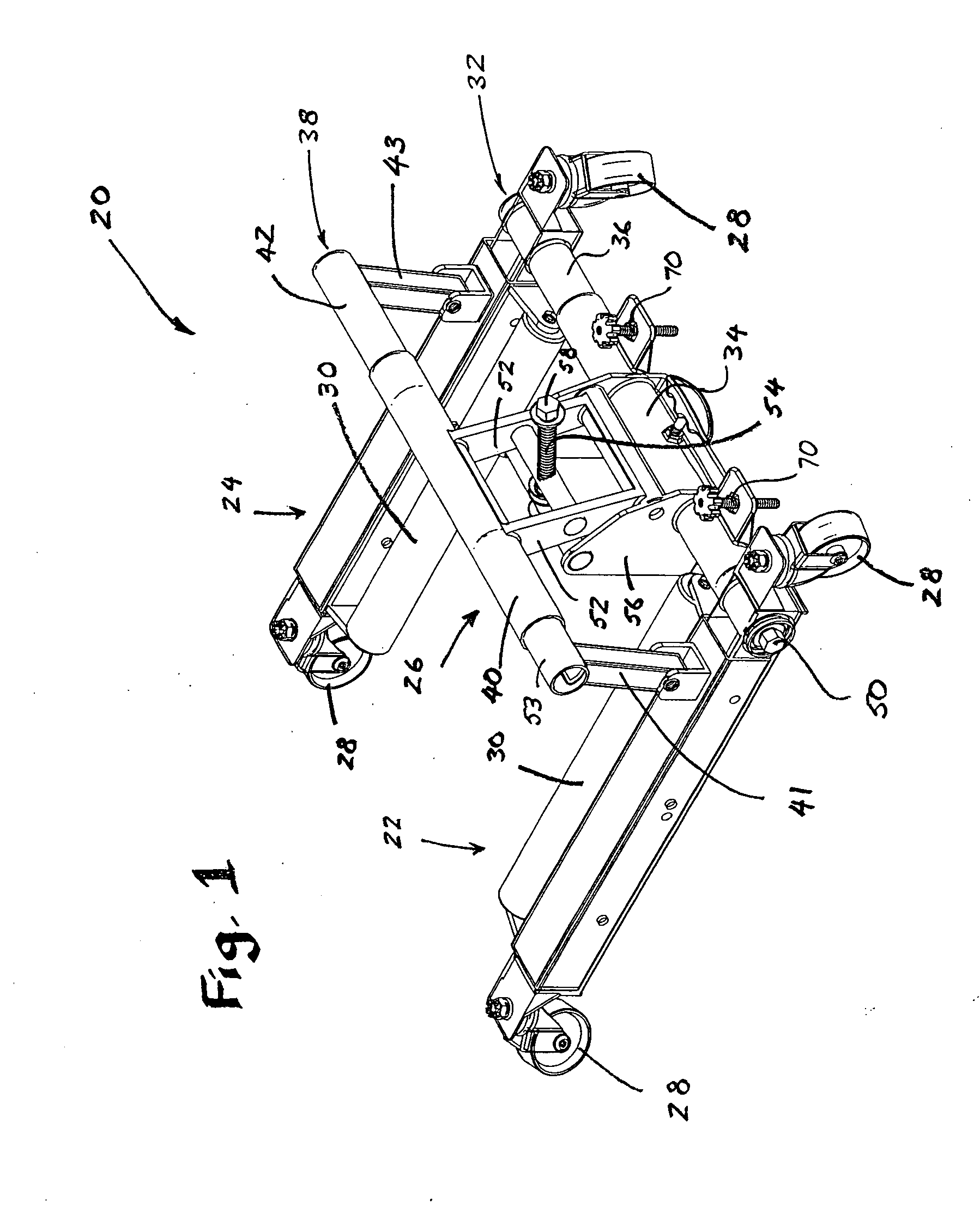
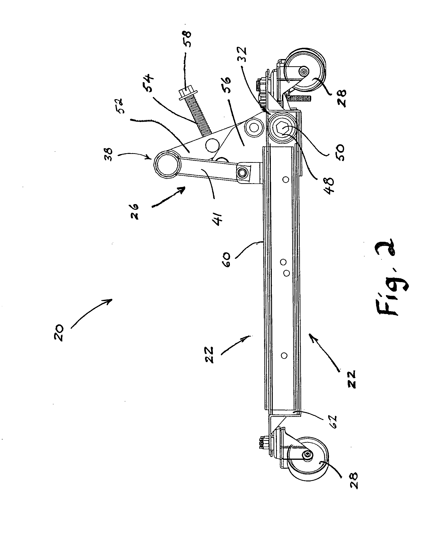
[0026]With reference to the drawings, which are provided by way of exemplification and not limitation, there is disclosed a wheel dolly suitable for using both as an automobile jack for holding heavy loads aloft for extended periods and to manipulate wheels, having features of the present invention.

[0027]In a preferred embodiment of the present invention, a wheel dolly, generally characterized by the numeral 20, is formed into a U-shape (when viewed from above as in FIG. 4 and FIG. 8) by two parallel support arms, left arm 22 and right arm 24. The base of the U-shape is closed by a base arm 26 (FIG. 4 and FIG. 8), connected to ends of the parallel support arms 22, 24. At each corner of the dolly 20 a caster 28 may be fixed, allowing the dolly to be easily moved about a horizontal floor surface, including when carrying a load. Each parallel arm 22, 24 includes a cylindrical roller 30, pinned by the ends of the roller to points of support on the support arm. The rollers 30 are configu...


PUM


Abstract

A wheel dolly is disclosed that is suited to serve as both an automobile jack, capable of holding large loads aloft for extended periods, relying on only mechanical systems and eliminating hydraulic systems. In a further aspect, the wheel dolly of the present invention does not include extended arms, handles, or levers for pumping or rotating the lifting mechanisms. Each lifting element terminates in only a single nut exposed to the user. Preferably, each nut of each lifting system has the same plan dimensions as the other, thus providing the advantage of allowing the user to operate the dolly with a driver and only one socket.

Description

TECHNICAL FIELD OF THE INVENTION[0001]The present invention relates to mechanisms, such as wheel dollies, for manipulating heavy wheels for automobiles, trucks, and other vehicles. More particularly, the invention relates to a wheel dolly that is suitable also for use as an automobile jack, allowing an artisan to work beneath an automobile lifted by such a dolly.BACKGROUND TO THE INVENTION[0002]Wheel dollies are known in the art for lifting and moving heavy vehicular wheels. The wheels lifted by a dolly may be separate, or in pairs, and may be fixed to a vehicle. When all the wheels of a vehicle are lifted, if the dollies have their own caster wheels, the entire vehicle may be moved about a workshop to accommodate space requirements.[0003]Commonly, dollies may involve pinching two arms horizontally together toward the perimeter of a wheel. The two arms provide a net upward force vector (and two inward vectors that cancel each other out), the upward force vector lifting the wheel. Al...

Claims


Application Information

Patent Timeline
Patent Type & Authority Applications(United States)
IPC IPC(8): B60B29/00
CPCB60B29/002B66F7/0641B66F7/0625B66F5/02
Inventor HERNANDEZ, HECTOR RAY
Owner ALLTRADE TOOLS
Why Eureka
Try Eureka