Apparatus for deploying an air bag through a hard panel

a technology of airbags and hard panels, which is applied in the direction of pedestrian/occupant safety arrangements, vehicle components, other domestic objects, etc., can solve the problems of door and surrounding instrument panels, easy to break and/or tear seams in integrally formed doors, and the inability of klobucar et al. to disclose airbag doors or any other supplemental inflatable restraint components

Inactive Publication Date: 2005-10-18
COLLINS & AIKMAN PROD CO
View PDF19 Cites 41 Cited by
  • Summary
  • Abstract
  • Description
  • Claims
  • Application Information

AI Technical Summary

Benefits of technology

[0018]According to another aspect of the invention, a tubular channel is disposed along at least a portion of the air bag door perimeter. The tubular channel is disposed opposite an outer surface of the air bag door and vehicle panel. A second structural channel may be disposed adjacent and parallel to the first tubular channel with the perimeter disposed between the first and second tubular channels. One of the tubular channels is integrally formed with the door and the other tubular channel is integrally formed with the vehicle panel. The tubular channels confine tearing to the perimeter without adding a significant amount of material that can c

Problems solved by technology

One reason that current PSIR systems add on a separate air bag door in such applications is because it is difficult to cause a tear seam in an integrally formed door to break and/or tear in a predictable way under the sudden shock of a deploying air bag.
Even when weakened, a te

Method used


Image

  • Apparatus for deploying an air bag through a hard panel
  • Apparatus for deploying an air bag through a hard panel
  • Apparatus for deploying an air bag through a hard panel

Examples


first embodiment

[0079]The four fastener brackets 70 that attach the first tether 50′ to the door 16′ extend integrally inward from the door inner surface 38′ adjacent a lower marginal region of the door 16′ to a point adjacent the reaction plate 28′. Similar to the ribs 40 of the first embodiment, the fastener brackets 70 present the reaction plate lower panel 42′ in a plane more perpendicular to the direction of air bag 24′ deployment from the dispenser 20′. In other words, the fastener brackets 70 span the space between the outwardly curved lower marginal door region and the generally vertical reaction plate lower panel 42′.

[0080]The single continuous tether sheet that includes the first flexible tether 50′ also includes a second flexible tether, generally indicated at 80 in FIGS. 4 and 7. The second tether 80 has an inner end portion 82 fastened to the air bag dispenser assembly 20′ at the tether control point 56′. In other embodiments, the second tether 80 may be secured either to the panel 12′...

third embodiment

[0088]According to the invention shown in FIGS. 9–11, the frangible marginal edge 18″ defines the entire perimeter of the air bag deployment door 16″. In other words, the frangible marginal edge 18″ extends completely around the air bag deployment door 16″ in an unbroken circuit as is best shown in FIG. 9. A pair of flexible tethers, representatively indicated at 50″ in FIGS. 10 and 11, is fastened between the air bag deployment door 16″ and the reaction plate 28″. Each tether 50″ includes an inner end portion 82″ fastened to the door 16″, an outer end portion 84″ fastened to the door 16″ and a middle portion 83 fastened to the reaction plate 28″ between the second hinge line 102″ and the reaction plate outer marginal edge 32″. The middle portion 83 of each tether 50″ is disposed approximately midway between the inner 82″ and outer 84″ end portions of each tether 50″.

[0089]The air bag deployment door 16″ includes only four of the fastener brackets 70″ disposed in a rectangular patte...

second embodiment

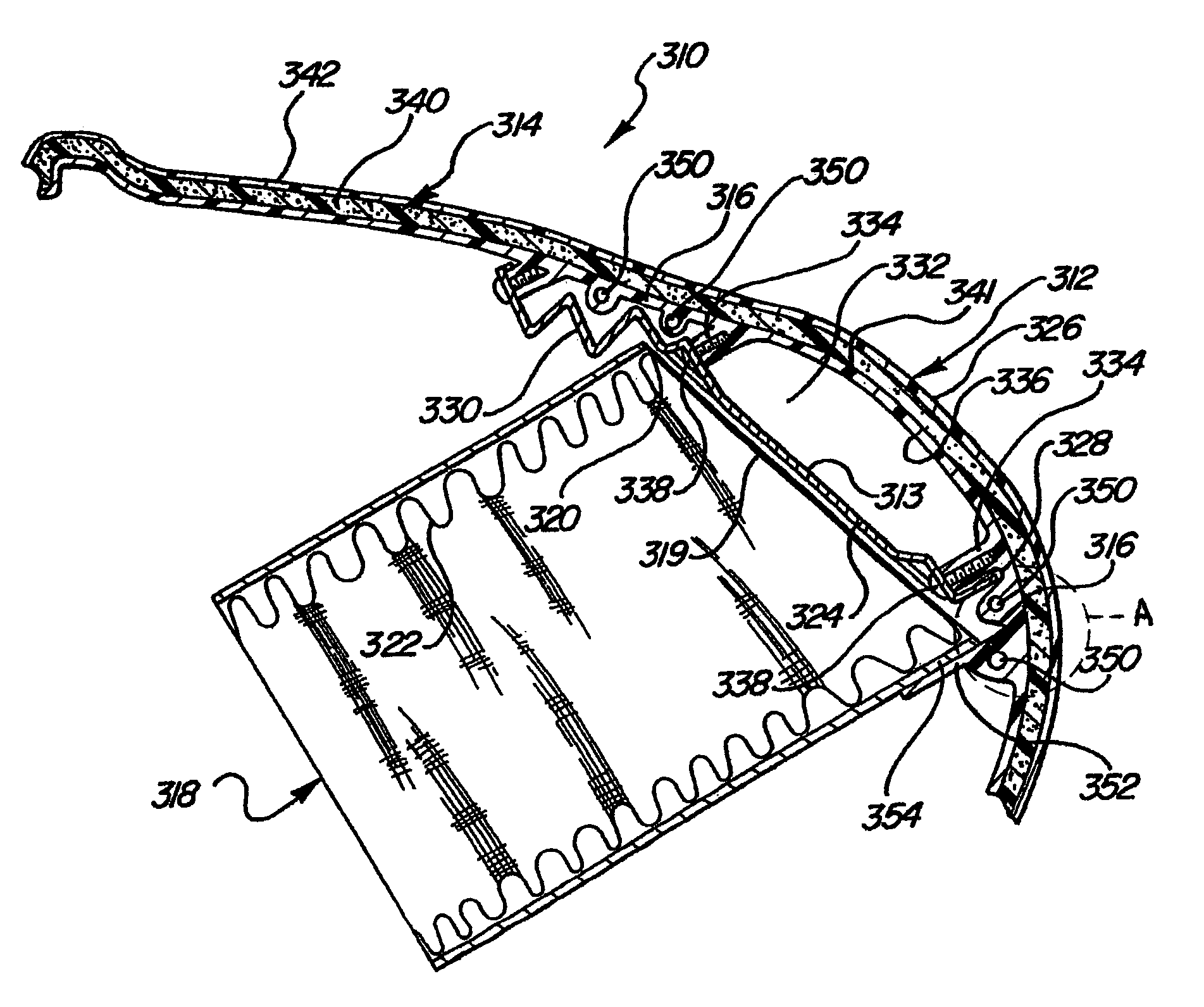
[0098]As with the first and second embodiment, a generally rectangular reaction plate 28s is attached to an air bag dispenser assembly 20s along a reaction plate inner edge 34s, as shown in FIGS. 12–15. An outer portion 35s of the reaction plate 28s is outwardly pivotable away from the air bag dispenser assembly 20s by bending the reaction plate 28s along a hinge line 36s extending parallel to the reaction plate inner edge 34s. Prior to air bag inflation, the reaction plate 28s is bent at the hinge line 36s approximately 850 downward from horizontal. Following air bag inflation, the reaction plate 28s is bent approximately 850 upward from horizontal.

[0099]Each flexible tether 50s, 51s has a length extending between first and second tether ends, representatively shown at 156 and 158, respectively, in FIGS. 12 and 13. The first and second tether ends 156, 158 of each flexible tether 50s, 51s are fastened to the air bag dispenser assembly 20s adjacent the reaction plate inner edge 34s ...


PUM

PropertyMeasurementUnit
Angleaaaaaaaaaa
Forceaaaaaaaaaa
Flexibilityaaaaaaaaaa

Abstract

An apparatus for deploying an air bag through an automotive dash panel (12) includes an air bag door (16) integrally formed in the panel and defined by a door perimeter including a frangible edge (18) of reduced cross section. A dispenser (20) supports the air bag (24) behind the door. A metal reaction plate (28) is positioned between the air bag (24) and the door (16). When the air bag inflates, it forces the reaction plate (28) to bend around a horizontal hinge line (36). As the reaction, plate pivots it concentrates inflation force along a lower portion of the frangible door edge. This helps to predictably separate the door from the dash panel by tearing along the lower door edge and allowing the tear to propagate up two side edges. In one embodiment, the tear also propagates across an upper edge to completely separate the door from the panel. At least one, and preferably two or three tethers (50) limit how far the door can travel during air bag inflation. A stop member may be included to limit reaction plate bending. After deployment, the reaction plate remains in a position that prevents the door from returning to its original position. A retaining structure may be included to preclude at least a portion of the air bag door from tearing free of the vehicle panel. A hinge (44) may be embedded in the panel in a position spanning a portion of the door perimeter. A hollow channel may be formed into the panel along the frangible marginal edge to create a substantial strength differential with the door perimeter to promote bending along the hinge and/or to help confine tearing to the frangible marginal edge during air bag deployment.

Description

[0001]This application is the National Stage of International Application No. PCT / US99 / 13592, filed Jun. 16, 1999, which is a Continuation in Part of U.S. patent application Ser. No. 08 / 949,842, filed Oct. 14, 1997, U.S. Pat. No. 5,941,558, which is a Continuation in Part of U.S. patent application Ser. No. 08 / 871,243, filed Jun. 9, 1997, now abandoned. This application also claims priority of U.S. provisional application Ser. No. 60 / 089,836 filed Jun. 19, 1998 and Ser. No. 60 / 089,863 filed Jun. 19, 1998.TECHNICAL FIELD[0002]This invention relates generally to a passive supplemental inflatable restraint (PSIR) system having an air bag door that is integrally formed with an instrument panel and, more particularly, to such a system having an air bag door integrally formed with a hard first-surface instrument panel and configured to break and / or tear open in a predictable way.BACKGROUND OF THE INVENTION[0003]An inflatable restraint system having an air bag door that is integrally forme...

Claims


Application Information

Patent Timeline
IPC IPC(8): B29C45/14B29C45/17B60R21/20B60R21/205B60R21/21B60R21/215B60R21/216B60R21/2165B60R21/217
CPCB29C45/14B29C45/1704B60R21/205B60R21/216B60R21/2165B60R21/215B29L2031/3038B60R21/21B60R2021/2163B60R21/2171B60R2021/21537
Inventor LABRIE, CRAIG B.STAWICKI, EDWIN V.MORREN, NELSON J.KENNEDY, JOHN J.DANIELS, VERNON A.ROGERS, JIMMY C.GRAY, JOHN D.BATCHELDER, BRUCE A.GALLAGHER, MICHAEL J.RHODES, JR., RICHARD D.
Owner COLLINS & AIKMAN PROD CO
Why Eureka
Try Eureka