
Remote control assembly comprising a signal light and a spotlight

a technology of remote control and signal light, which is applied in the direction of lighting applications, lighting support devices, and with built-in power, can solve the problems of inconvenience in use in some cases, and achieve the effect of good weatherproof design and good sealing performan

Inactive Publication Date: 2005-10-18
YUK FAT
View PDF6 Cites 44 Cited by
  • Summary
  • Abstract
  • Description
  • Claims
  • Application Information

AI Technical Summary

Benefits of technology

[0004]The other purpose of the present invention is to provide a remote control combined signal light and spotlight which is weather proof and can provide stronger flash light and illumination.
[0015]In the above-mentioned remote control combined signal light and spotlight, the driving device for the upward and downward rotation of the combined light further includes a control mechanism for allowing the combined light to rotate upward and downward in a reciprocating manner, said control mechanism includes an elongated positioning operation rod which is pivotally mounted on the outer wall of the housing, and two miniature limit switches or miniature switches mounted on the housing with a predetermined interval and a certain angle of inclination between each other and an up-down actuating means which can allow the lower portion of the positioning operation rod to swing periodically to make contact with the contacts of the two miniature switches and which can make the first motor rotate upward and downward periodically in forward and reverse direction.
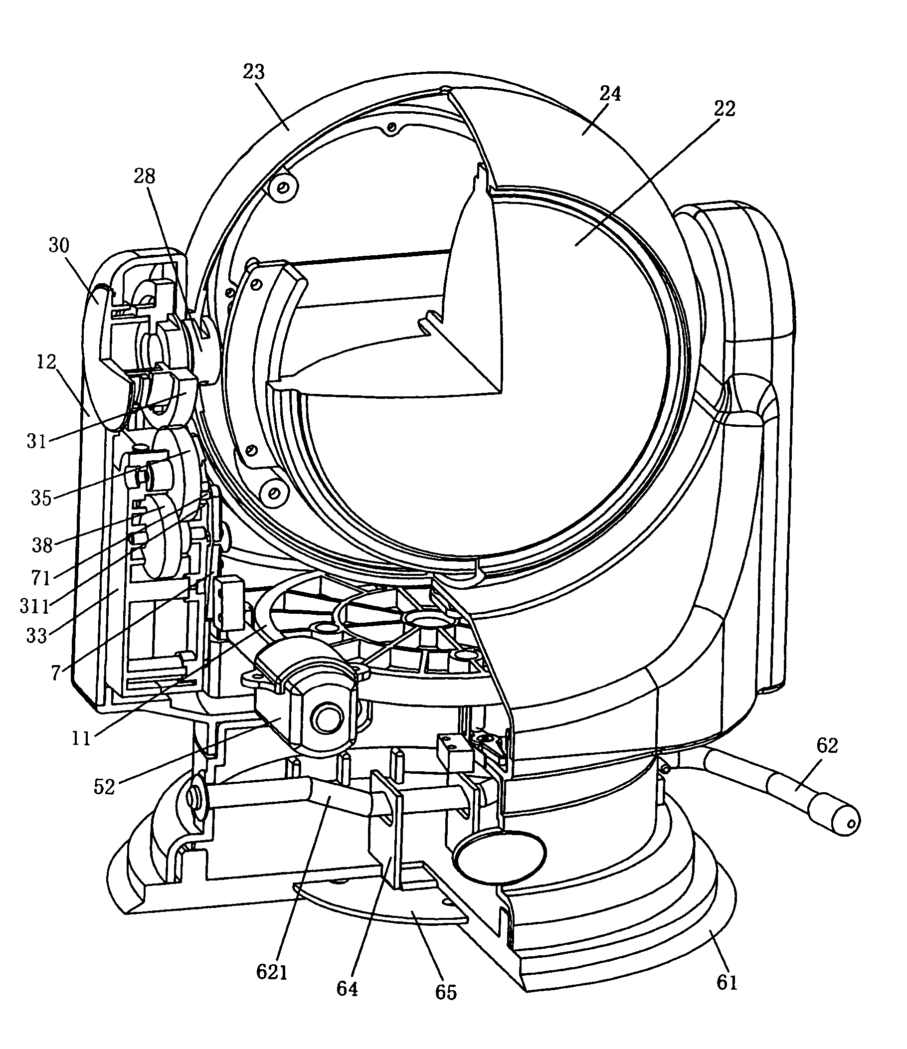
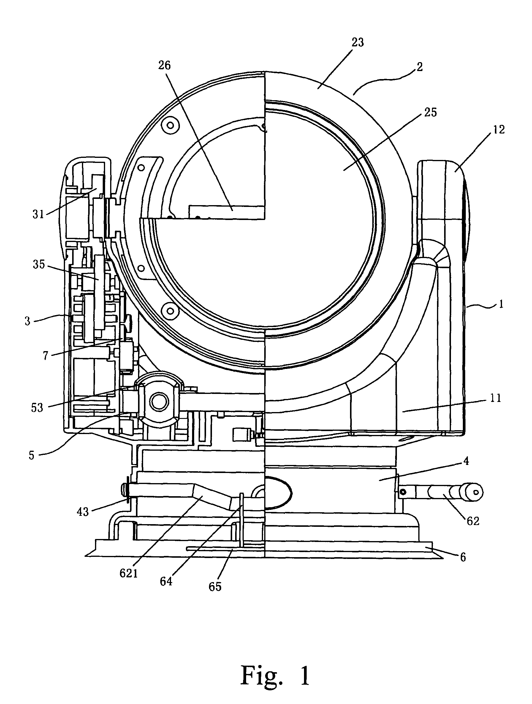
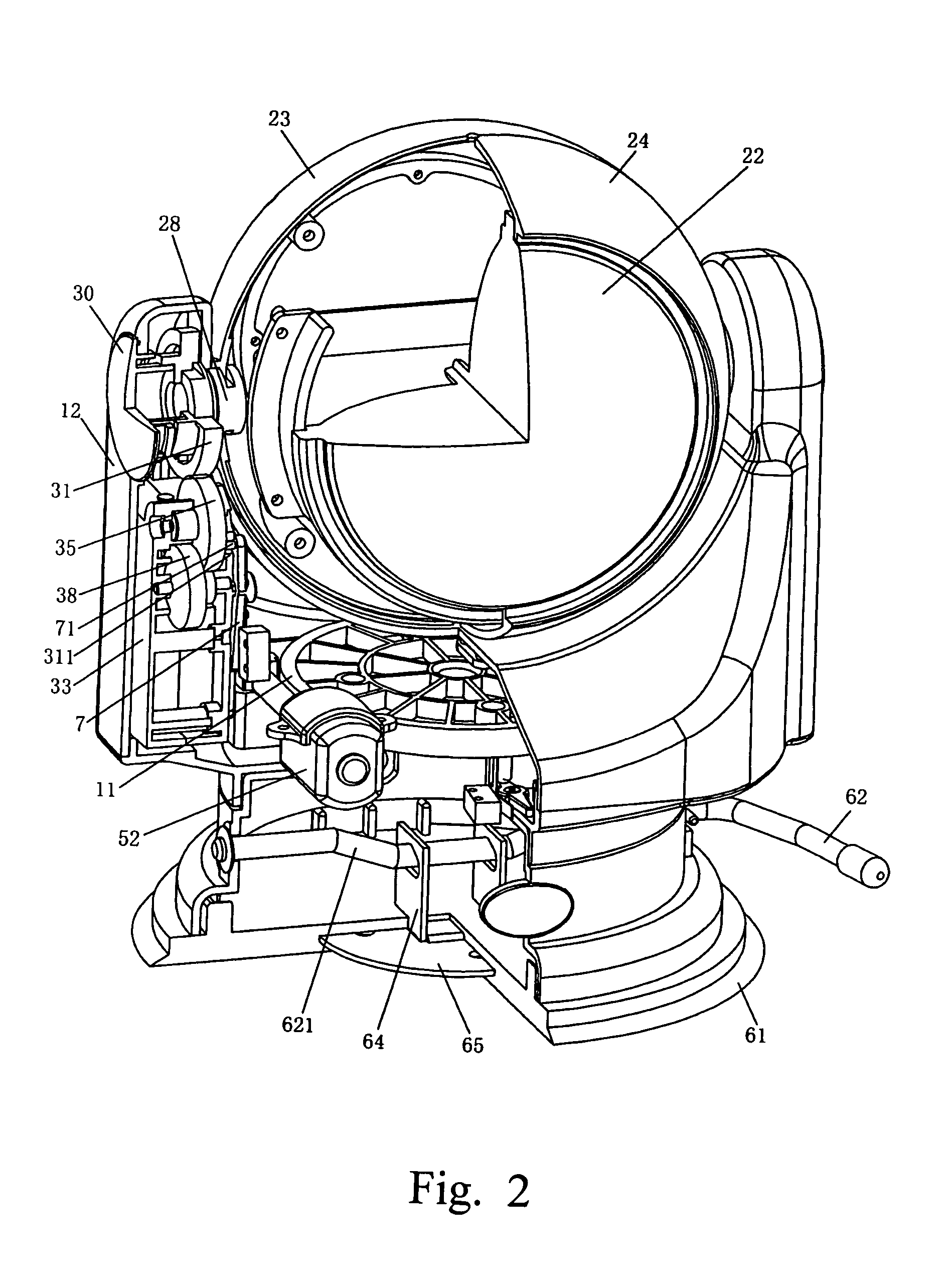
[0017]It can be seen form the above, due to the fact that the remote control combined signal light and spotlight adopts a combined light which can be formed into a ball like shape, and a driving device for upward and downward rotation composed of driven gear mounted on the two supporting shafts of the combined light and a first drive mechanism which is mounted in the lamp receptacle supporting portion and which can make the driven gear rotate as well as a driving device for horizontal rotation of the combined light mounted on the base portion, the combined lights can rotate upward and downward in a range of 250°, and can rotate left to right in a super wide range of 360°, and can provide a large visual angle, even more than 90° in the evening or at night. In addition, the combined light adopts super bright sealed light beam bulb and super bright xenon flash bulb, in the case of emergency, the flash light can be seen from several kilometers. The combined light, not only has the good sealing performance, but also is of a good weather proof design. The structure of the combined light makes the signal light and the spotlight being able to work simultaneously or work independently, moreover the combined light can be used outdoor such as on deck, galley, trailers and various utility vehicles, and the suction disk of the equipment can provide powerful holding function.

Problems solved by technology

Such rotation transmission structure suffers from the complexity of gear processing, mounting and sealing and the requirement for higher power motor, in addition the upward and downward rotation angle with which the lamp unit rotates around the base support member or around the supporting shaft is limited by the gear rack type transmission, it is believed that the rotation angle cannot exceed ±45°.
Furthermore, in the prior art, the illumination and the signalling apparatuses are generally designed independently and separately, they have not be integrated into one body, thereby inconvenience arises in use in some cases.

Method used


Image

  • Remote control assembly comprising a signal light and a spotlight
  • Remote control assembly comprising a signal light and a spotlight
  • Remote control assembly comprising a signal light and a spotlight

Examples


Embodiment Construction

[0021]Referring to FIG. 1 to FIG. 3, the remote control type combined signal light and spotlight includes a lamp receptacle 1, a combined light 2, a driving device 3 for the upward and downward rotation of the combined light 2, a base stand 4, a driving device 5 for the horizontal rotation of the combined light 2, a suction disk device 6 and several receiving and controlling circuit boards. Among them, the lamp receptacle 1 includes a base portion 11 and two supporting portions 12 disposed at two sides of the base portion 11. The supporting portions 12 are perpendicular relative to the plane where the bottom of the base portion 11 is positioned. In addition, the supporting portions 12 are hollow pillars or columns, a shaft hole 13 is provided each on the upper portion thereof. The shaft holes 13 can be of step shape.

[0022]The combined light 2 comprises a signal light 21, a spotlight 22, a front lamp shield 23, a rear lamp shield 24, a lens 25, a signal light circuit board 26 and two...


PUM


Abstract

A remote control assembly comprising a signal light and a spotlight comprises a lamp receptacle, a combined light, two driving device for the combined light, a base stand, circuit board and suction disk. The combined light includes signal light and spotlight, lamp shields, lens and supporting shafts. When assembled, it is rotatably mounted in the lamp receptacle. One of driving device can make the combined light rotate upward and downward in the range of 250°, and can provide large visual angle in the evening or at night, even beyond 90°, and the other driving device can make the combined light rotate horizontally in the wide range of 360°. In addition, it (the combined light) has good performance of weather proof and super bright illumination. In emergency condition, its flashing light can be seen from several kilometers away. It is suitable for use on deck, galley, trailers and utility vehicles.

Description

FIELD OF INVENTION[0001]The present invention relates to an assembly comprising an illumination and signalling apparatus, particularly relates to a remote control type combined signal light and spotlight.BACKGROUND OF THE INVENTION[0002]In the U.S. Pat. No. 5,490,046, a portable remote-controlled searchlight apparatus is disclosed. The apparatus includes a lamp unit, a lamp housing, a base support member, remote control unit and a releasable attachment to mount and demount the base support member to another surface, such as on the roof of a motor vehicle. The searchlight apparatus or lamp unit can be rotated upward and downward or left and right side by means of remote control unit mounted within the vehicle. The left and right side rotation of the searchlight apparatus or the lamp unit is realized by the engagement of an inner gear disk and an outer gear separately mounted between the lamp housing and the base support member, while the upward and downward rotation is realized by mo...

Claims


Application Information

Patent Timeline
Patent Type & Authority Patents(United States)
IPC IPC(8): F21S8/00B60Q1/24
CPCB60Q1/245F21S8/003F21V21/092F21V21/15F21V21/30F21W2111/00F21Y2103/00F21V23/045
Inventor LUI, THOMAS KIM FUNG
Owner YUK FAT
Learn More