Double-ended high-power gas discharge lamp

A gas discharge lamp, high-power technology, applied to the parts of gas discharge lamps, etc., can solve the problems of easy looseness of the lamp head, unsafe use, high temperature, etc., to improve light output efficiency, safe and reliable use, and prolong use The effect of longevity

Inactive Publication Date: 2012-06-20
NINGBO YAMAO OPTOELECTRONICS CO LTD
View PDF6 Cites 0 Cited by
  • Summary
  • Abstract
  • Description
  • Claims
  • Application Information

AI Technical Summary

Problems solved by technology

[0002] After the existing double-ended gas discharge lamp has been working for a long time, the temperature at both ends of the glass tube lamp cap is very high, and the mechanical strength is poor, so the lamp cap is easy to loosen, and the direct connection with the power supply is the lead wire in the glass material, and the outer The glass bulb is easily broken, which directly affects the service life of the gas discharge lamp
[0003] Patent No. CN201020271581.X "Double-ended high-power high-pressure sodium lamp" also discloses a slender tube-shaped, small-sized double-ended high-power high-pressure sodium lamp, but the glass tube lamp caps at both ends are connected to the power supply by glass parts. The mechanical strength is poor, the temperature is high, and it is easy to break. In addition, the lead wire is made of multi-strand metal guide wires, which are easy to loose, easy to break, and easy to deform. The small contact surface with the power supply has poor electrical performance and is unsafe to use.

Method used


Image

  • Double-ended high-power gas discharge lamp
  • Double-ended high-power gas discharge lamp
  • Double-ended high-power gas discharge lamp

Examples


Embodiment Construction

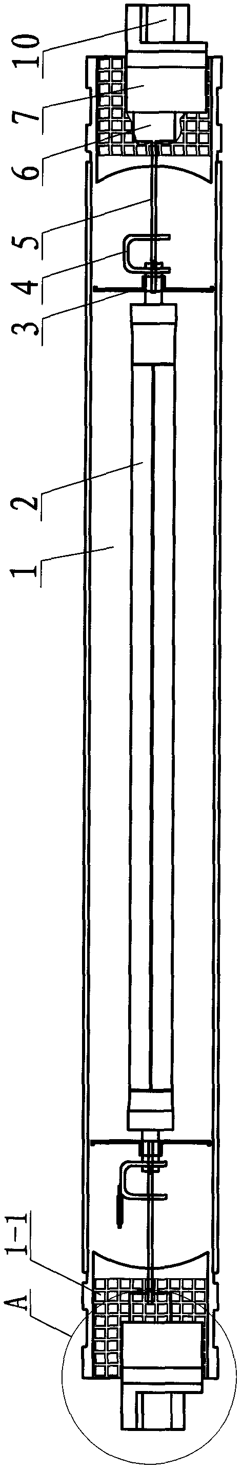
[0012] The embodiments of the present invention will be described in further detail below in conjunction with the accompanying drawings.

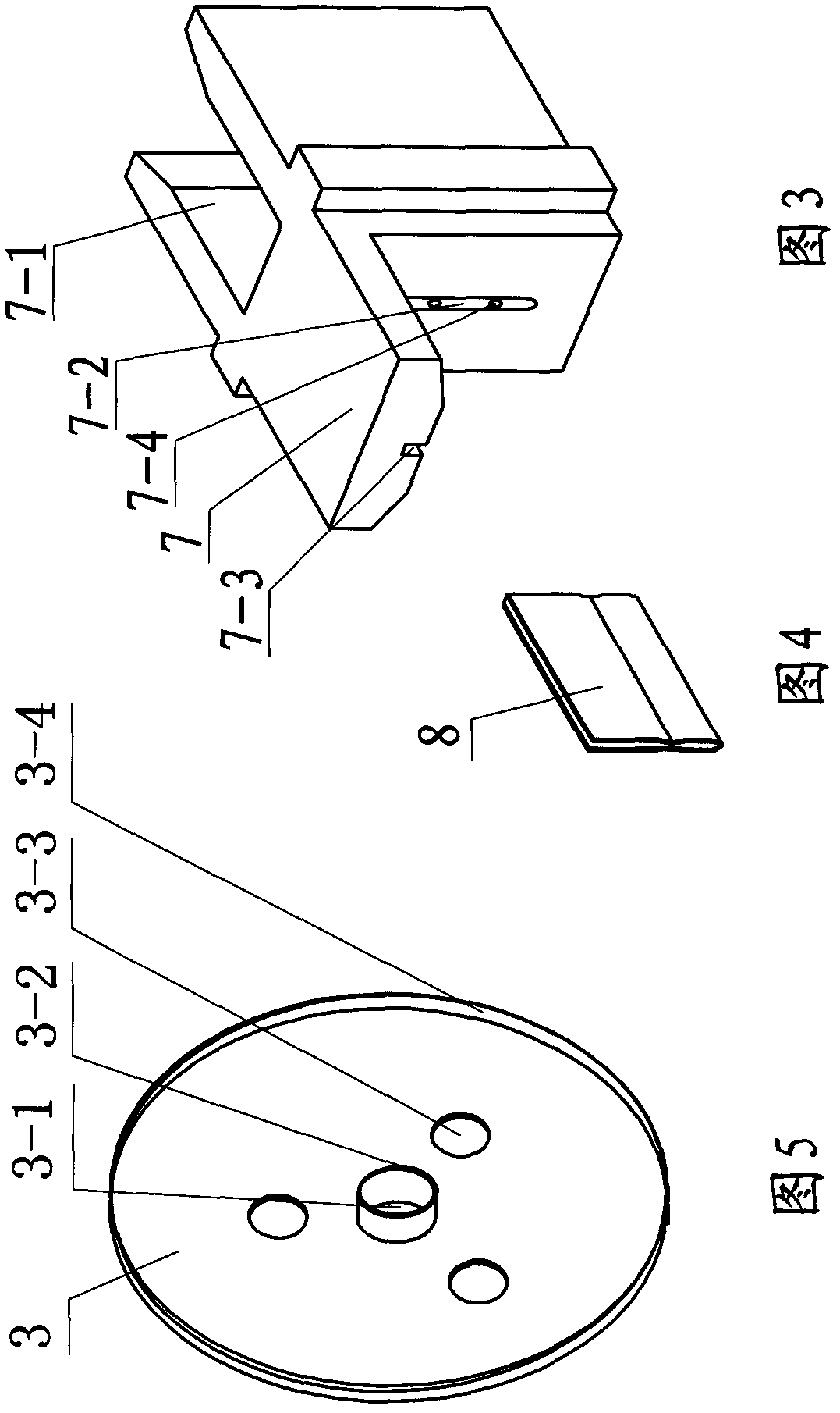
[0013] The supporting piece 3 is a whole disc shape, made of bright metal or stainless steel. There is a supporting hole 3-1 in the middle. The hole edge has a hole flanging 3-2 in the same direction as the flanging 5, and the supporting hole edges are evenly distributed. The expansion hole 3-3 facilitates the thermal expansion and contraction of the material without deformation. There are flanges 3-4 perpendicular to the wafer and smooth surface around the support sheet to increase the mechanical strength of the support sheet, such as Figure 5 Shown.

[0014] The clip 8 is made of stainless steel and has indentations on both surfaces, such as Figure 4 Shown.

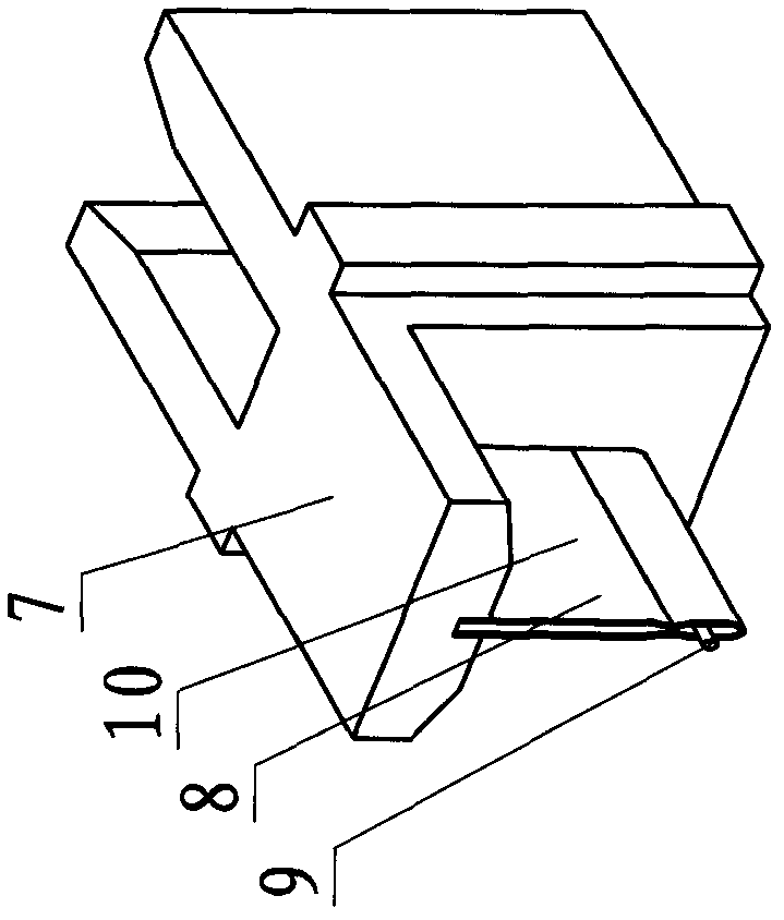
[0015] Porcelain head 7 is made of insulating material with temperature resistance, humidity resistance and high dielectric strength. There is a short groove 7-2 on the left vertical sur...


PUM


Abstract

The invention discloses a double-ended high-power gas discharge lamp, which comprises a discharge tube, wherein the discharge tube is arranged in a glass tube, and a supporting piece is arranged at each of the two ends of the discharge tube. Molybdenum rods are connected to the discharge tube, and each molybdenum rod comprises a nickel wire, a molybdenum piece and a leading-out wire. The leading-out wire is clamped between clamping pieces to form a leading-out wire clamping piece. A porcelain head is fixed at each of the two ends of the glass tube. The leading-out wire clamping pieces are correspondingly fixed on the porcelain heads. The shape of the supporting piece is matched with that of the section of the glass tube. The edge of the supporting piece is upturned. Extension holes are formed in the surface of the supporting piece. A support hole is formed in the center of the supporting piece. Both the supporting pieces are wholly disc-shaped, shade light rays on the two sides of the discharge tube and reflect the light rays onto a reflector in a centralized way so as to achieve high luminous flux and illuminance, improve the light output efficiency of the lamp, control temperature at each of the two ends of the glass tube at about 50 DEG C and realize supporting, fixation, thermal insulation and reflection functions. The porcelain heads have strong mechanical strength, protect the ends of the glass tube from being cracked, and prolong the service life of the glass tube. The leading-out wire clamping piece is safe and convenient to operate and use, is directly inserted into a power socket, has a small electrical contact surface, strong mechanical strength and electrical performance, and greatly reduces heating phenomena.

Description

Technical field [0001] The invention relates to a gas discharge lamp, in particular to a double-ended high-power gas discharge lamp with high mechanical strength and good electrical performance. Background technique [0002] After long-term operation of the existing double-ended gas discharge lamp, the temperature at both ends of the glass tube lamp cap is very high, but the mechanical strength is poor, so the lamp cap is easy to loosen. At the same time, the direct connection with the power source is the lead wire in the glass material. The glass bulb is fragile, which directly affects the service life of the gas discharge lamp. [0003] Patent No. CN201020271581.X "Double-ended high-power high-pressure sodium lamp", although it also discloses a slender tube-shaped, small-sized double-ended high-power high-pressure sodium lamp, but the glass tube lamp caps at both ends are connected with the power supply by glass. The mechanical strength is poor, the temperature is high, and it i...

Claims


Application Information

Patent Timeline
Patent Type & Authority Applications(China)
IPC IPC(8): H01J61/36H01J61/52
Inventor 陈晖施振家
Owner NINGBO YAMAO OPTOELECTRONICS CO LTD
Why Eureka
Try Eureka