Real-time residential energy monitor

a technology for monitoring devices and energy consumption, applied in the direction of analysing/displaying, instruments, electric devices, etc., can solve the problems of many problems of proposed devices, difficult for consumers to make immediate changes to energy consumption, and the majority of these devices cannot be legally used

Inactive Publication Date: 2005-10-18
M&M SYST
View PDF18 Cites 100 Cited by
  • Summary
  • Abstract
  • Description
  • Claims
  • Application Information

AI Technical Summary

Benefits of technology

[0008]The first objective of the present invention is to provide an energy monitor system which allows homeowners to monitor instantaneous power usage, history and projected future energy usage.

Problems solved by technology

It is very difficult for consumers to make immediate changes to the energy consumption by having to wait to the end of the month when they get a monthly bill in order adjust their energy usage.
These proposed devices have many problems.
A problem with these devices is that they are generally illegal in many jurisdictions which prohibit utility meters from being tampered with by obstructing and / or modifying the utility meter box itself.
Thus, most of these devices cannot be legally used.
Furthermore, the cost of the device components and extra labor time to install these devices makes them further impractical to be used.
Finally, many of these devices can obstruct the rotating disk so that meter readers are delayed from taking a reading when needed or emergency personnel cannot remove the meter if required during an emergency.
These devices have problems such as the alignment of the black mark line so that it can be read.
Additionally, these devices have inherent problems for false readings, and the like.
Furthermore, these devices do not give real-time readings since the monitor has to wait until the black line on the rotating disk passes by the sensor.
Furthermore, these hardwired systems can require that power to the residence be turned off during installation of the monitoring device.
Still furthermore, many of these devices can malfunction during power shortages, to the residence.
Portable proposed devices have other problems, For example, the portable monitoring devices are limited to professional meter readers, and cannot be adapted for residential use, and do not allow for displaying power usage, history usage, and projected future usage.

Method used


Image

  • Real-time residential energy monitor
  • Real-time residential energy monitor
  • Real-time residential energy monitor

Examples


Embodiment Construction

[0033]Before explaining the disclosed embodiments of the present invention in detail it is to be understood that the invention is not limited in its application to the details of the particular arrangements shown since the invention is capable of other embodiments. Also, the terminology used herein is for the purpose of description and not of limitation.

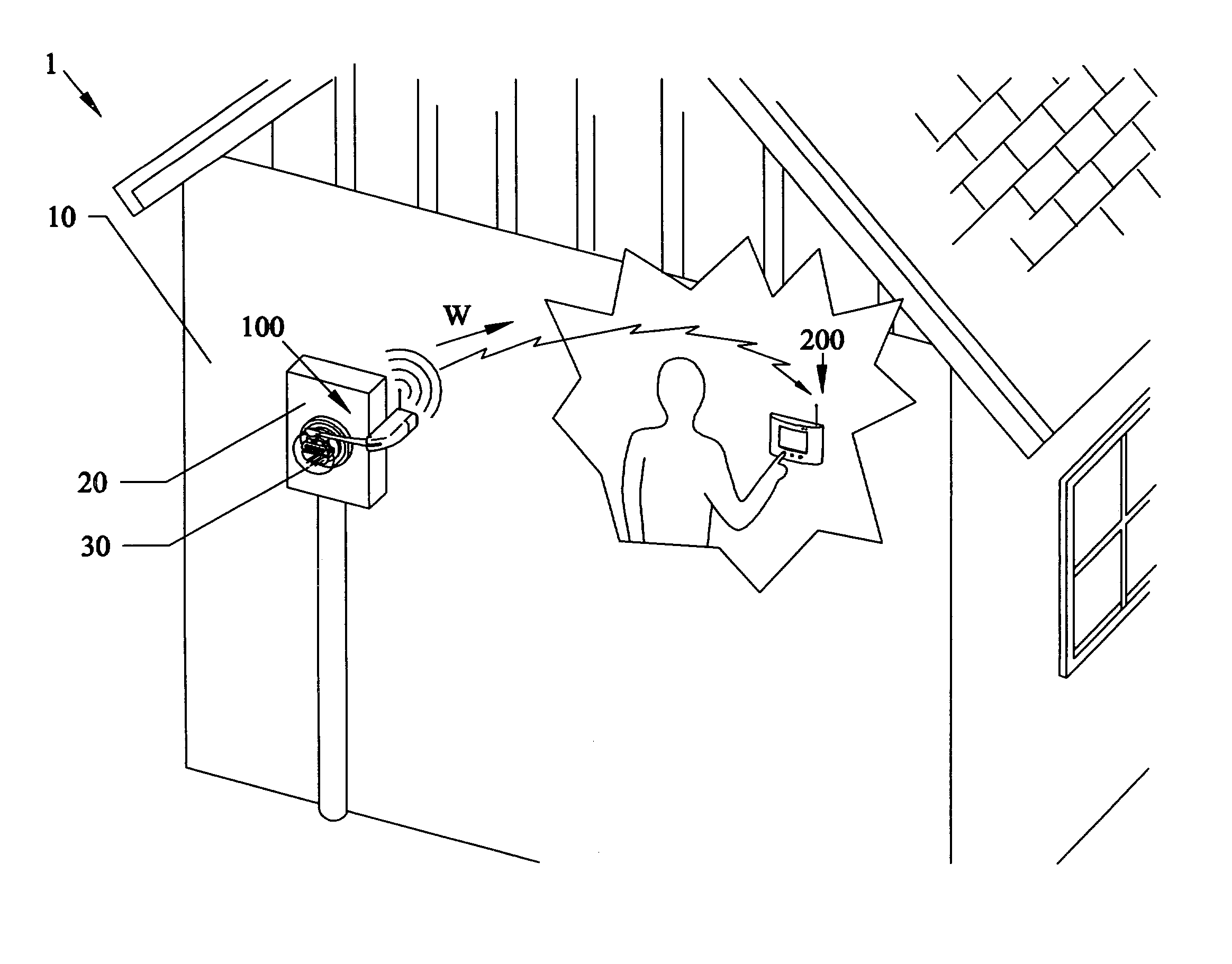
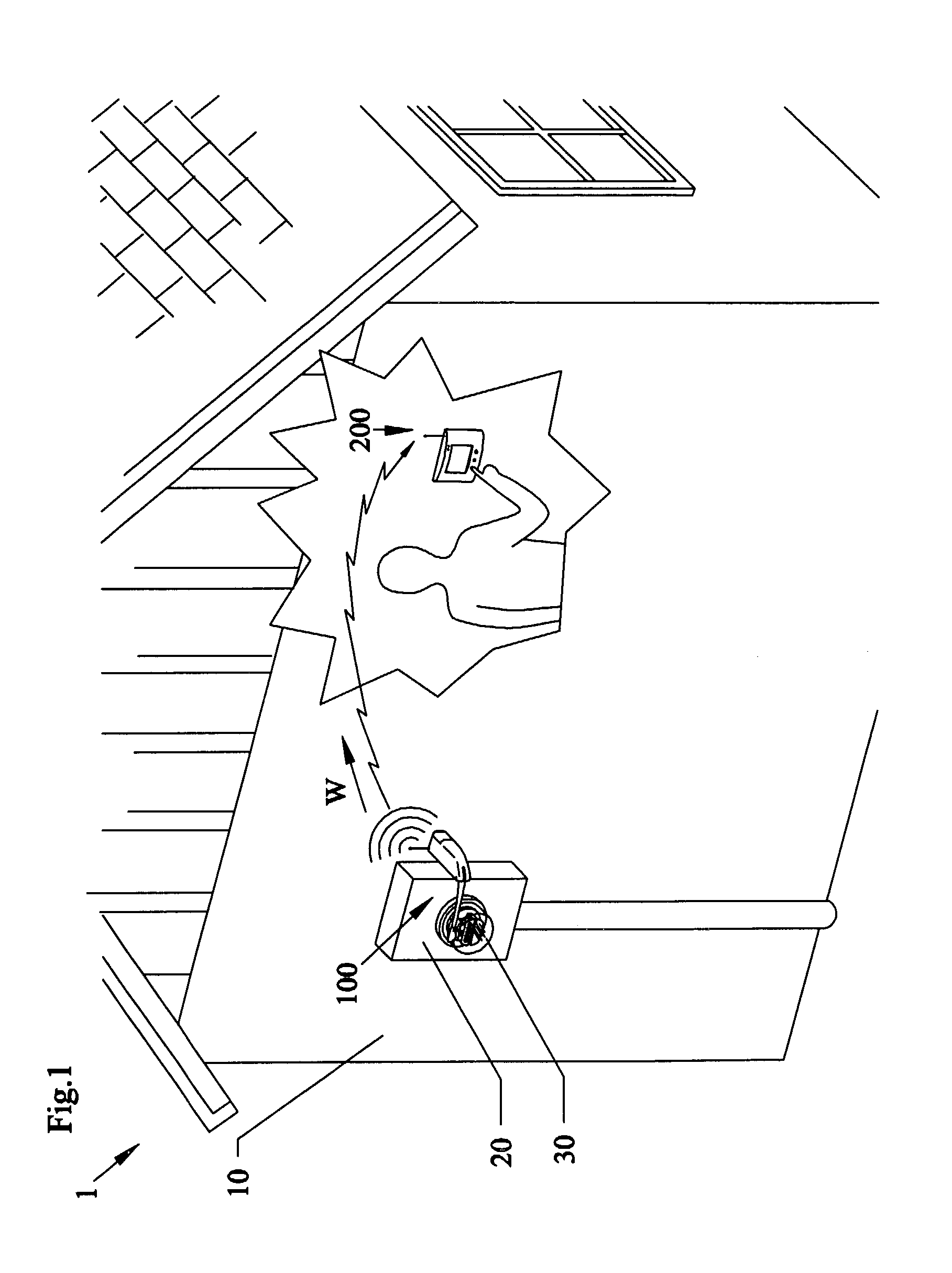
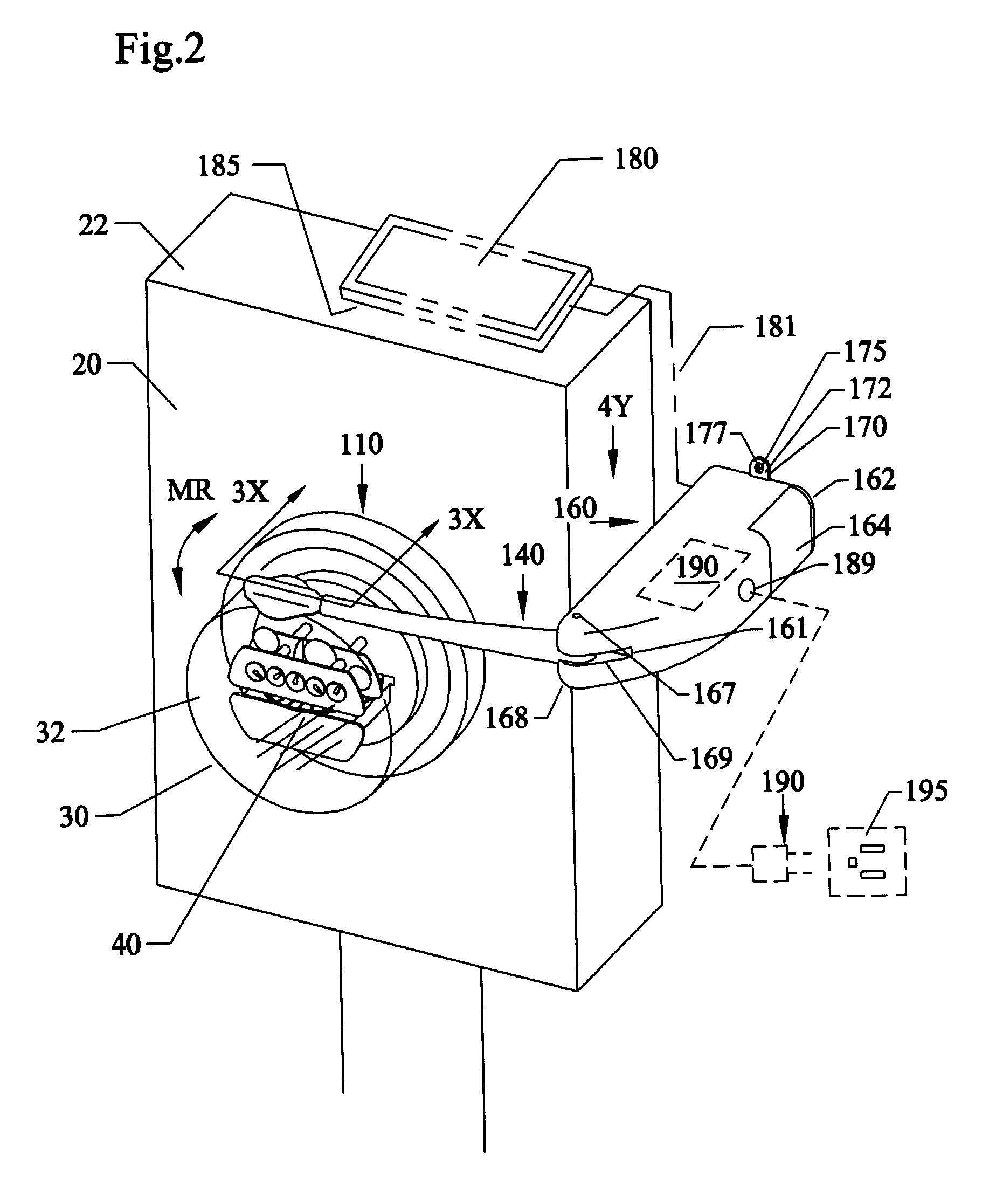
[0034]FIG. 1 shows a perspective exterior view of a novel outdoor monitor unit assembly 100 that can include power meter monitor 110 attached to a rotatable arm 140 with wall mount 160 adjacent to a power meter 20, 30 and cut-away view of an indoor display receiver / monitor 200. FIG. 2 is an enlarged perspective view of the meter monitor 110 and arm 140 of FIG. 1 adjacent to the power meter 20, 30. FIG. 3 is a front cross-sectional view of the meter monitor 110 and arm 140 of FIG. 2 along arrow 3X. FIG. 4 is a top view of the meter monitor 110 on rotatable arm 140 and wall mount 160 of FIG. 2 along arrow 4Y. FIG. 5 is an end view of t...


PUM


Abstract

An inexpensive energy monitoring device and method for measuring energy usage and power costs in real time. The invention can include an external type digital battery powered camera that can be mounted away from and adjacent to the outdoor utility meter on a rotatable arm, which can send data signals to remote locations indoors using wireless such as an RF signal to a detector / display inside the residence. The indoor unit can be programmed to display desirable energy status information to a home owner on power usage and power costs on a daily bases, monthly bases, and yearly bases so that the home owner can budget energy usage and energy costs as needed. A shield can also be used with device and method for shielding power meters from adverse weather conditions.

Description

[0001]This invention relates to optical sensors, and in particular to meter reader systems and methods having camera type sensors mounted adjacent and separate from a utility meter such as externally located electric and water meters, for accurately reading the utility meters and transmitting up to date information in a wireless manner into an adjacent business or residence for real-time energy usage monitoring and budget status.BACKGROUND AND PRIOR ART[0002]Homeowners have had a long felt need to monitor the daily energy consumption. Currently homeowners adjust their energy consumption by their past energy bills, such as evaluating a previous month's electric bill. It is very difficult for consumers to make immediate changes to the energy consumption by having to wait to the end of the month when they get a monthly bill in order adjust their energy usage.[0003]Various patents have been proposed over the years. See for example U.S. Pat. No. 4,204,115 to Boldridge, Jr.; U.S. Pat. No....

Claims


Application Information

Patent Timeline
Patent Type & Authority Patents(United States)
IPC IPC(8): G08C15/00G08C15/06G01D4/00
CPCG01D4/008G06Q50/06Y04S20/46Y04S20/30Y02B90/20G01D2204/18
Inventor DUCHARME, ALFRED D.EICHENHOLZ, JASON M.VALENTINE, PAUL A.
Owner M&M SYST
Why Eureka
Try Eureka