Method of providing visual continuity when panning and zooming with a map display

a map display and visual continuity technology, applied in surveying and navigation, navigation instruments, instruments, etc., can solve the problems of zooming, and difficult to know the relationship between the map views before and after panning

Inactive Publication Date: 2005-10-18
HERE GLOBAL BV
View PDF17 Cites 123 Cited by
  • Summary
  • Abstract
  • Description
  • Claims
  • Application Information

AI Technical Summary

Benefits of technology

[0009]To address these and other objectives, the present invention comprises a method for providing visual continuity when performing a zooming or panning operation with a graphical map shown on display screen of a computing platform. When a user of the computing platform operates the user interface thereof to perform a zooming or panning operation, a first map view of a first geographic area is replaced with a second map view of a second geographic area, such that at least a portion of the first and second geographic areas overlap. In order to provide visual continuity, a transition view is shown on the display screen of the computing platform between the showing of the first map view and the showing of the second map view. The transition view is shown for several seconds immediately after the user operates the user interface to perform the zooming or panning operation. The transition view includes either the first map view or the second map view. The transition view also includes a boundary line that is overlaid on the map view being shown. The boundary line is located on the map view used for the transition view to show the border of the portion of the other map view which is visible in the map view used for the transition view. For example, if the second map view is used for the transition view, the boundary line is rendered on the second map view showing the border of the portion of the first map view which is visible in the second map view. On the other hand, if the first map view is used for the transition view, the boundary line is rendered on the first map view showing the border of the portion of the second map view which is visible in the first map view. The method for providing visual continuity is particularly useful for in-vehicle navigation systems or hand-held devices with small display screens. The method can also be applied to text windows.

Problems solved by technology

Knowing the relationship between the map views before and after panning and zooming can be difficult, especially on computing platforms that do not support smooth panning and zooming.
Even on computing platforms that support smooth panning and zooming, it is sometimes difficult to know the relationship between the map views before and after panning and zooming.

Method used


Image

  • Method of providing visual continuity when panning and zooming with a map display
  • Method of providing visual continuity when panning and zooming with a map display
  • Method of providing visual continuity when panning and zooming with a map display

Examples


first embodiment

II. First Embodiment

[0026]The first embodiment provides visual continuity when panning or when zooming out. According to this embodiment, when performing a zooming or panning operation, visual continuity is provided by modifying the display in two steps. These two steps are performed in sequence, i.e., one after the other. The first step includes the presentation of a transition view. The transition view lasts several seconds. In this embodiment, the transition view includes the new view, but with the addition of a superimposed rectangle (or line) that corresponds to the boundaries (e.g., borders) of the old view. In the second step, which occurs a few seconds after the first step, the superimposed rectangle (or line) disappears leaving only the new view. The superimposed rectangle, which is shown during the transition view, provides visual continuity so that the user can locate whatever he / she was looking at before the map shifted.

example 1

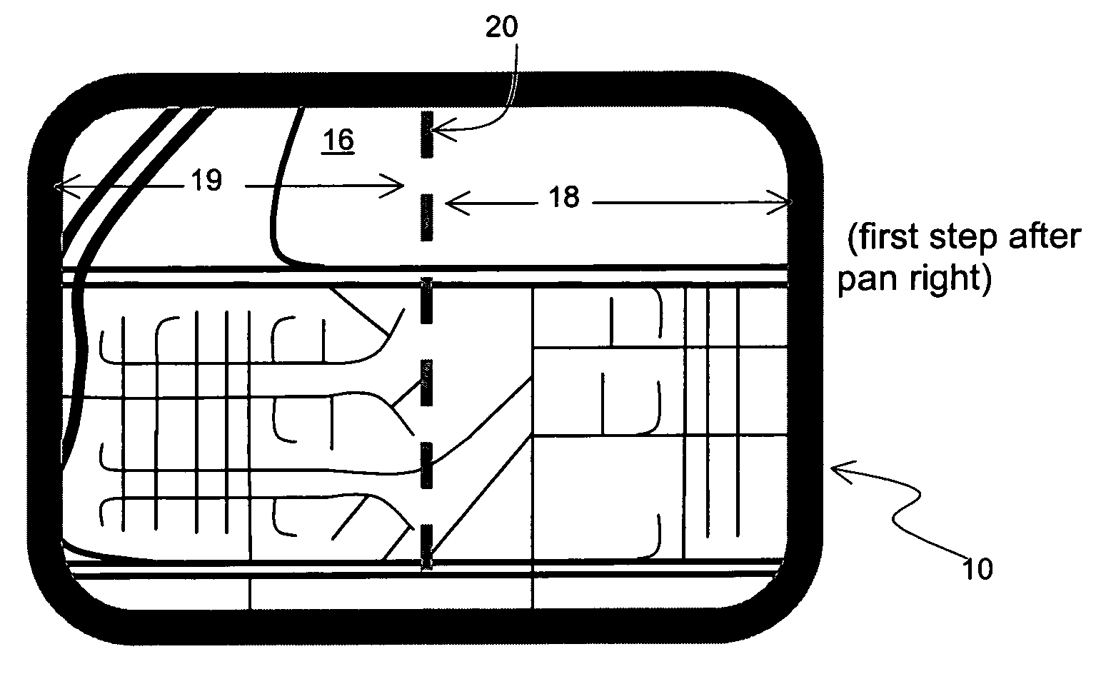
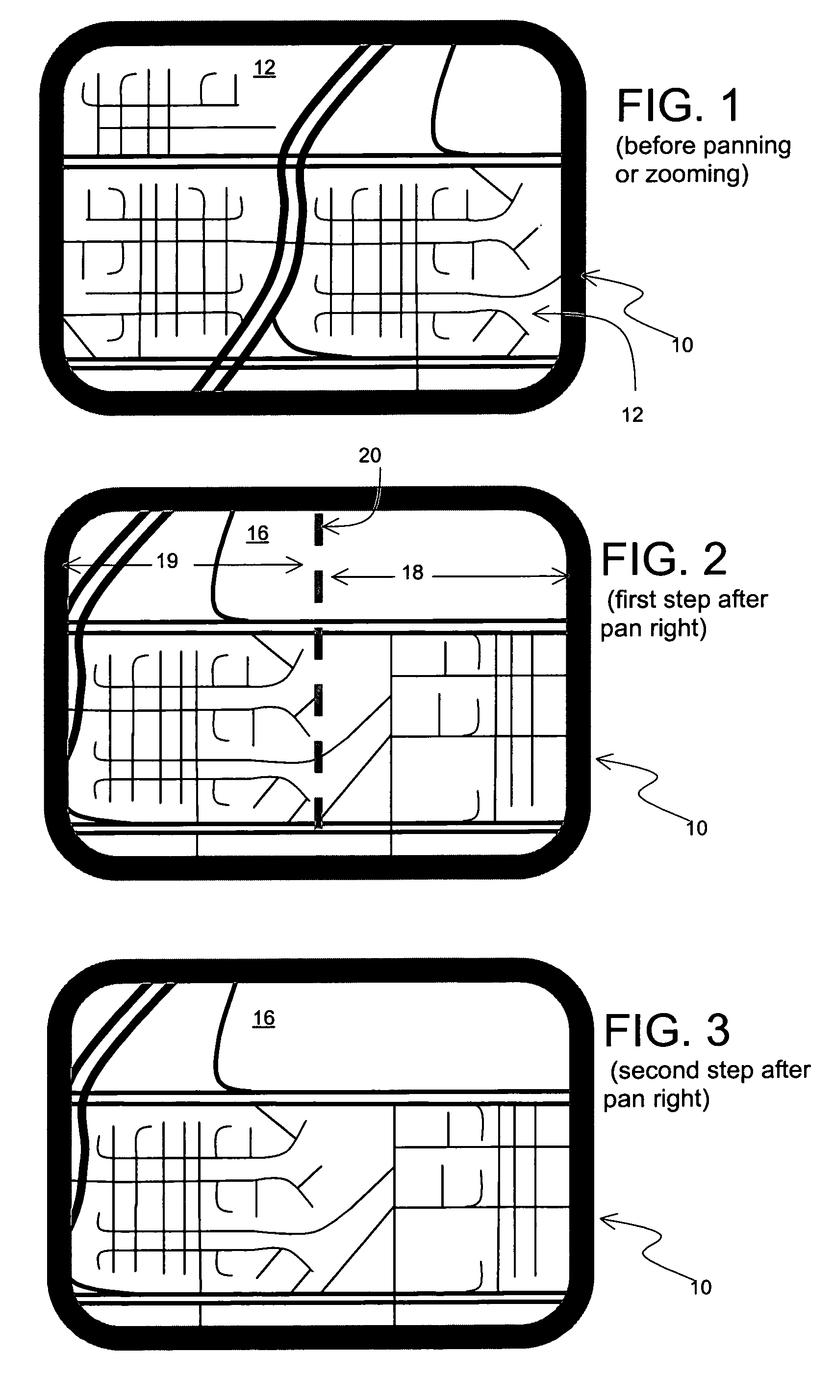
[0027]FIG. 1 shows a display screen 10 of a computing device showing a graphical map 12 of a geographic area before performing a panning or zooming operation. Using controls of the computing device, the user pans right. FIG. 2 shows the transition view on the display screen 10 of the computing platform in the first step after the user performs the operation of panning to the right. In the transition view on the display screen 10 is a new graphical map 16. In this case, the new view 16 displays new material on the right side 18 of the screen 10. On the left side 19 of the view 16 on the display screen 10 is a portion of the same material that was visible prior to panning.

[0028]In order to provide visual continuity, a boundary line 20 defining the limits of the old view is rendered on the new view 16. Because the panning operation is directly horizontal, the boundary line 20 is a vertical line running from the top of the display screen 10 to the bottom.

[0029]FIG. 3 shows the second st...

example 2

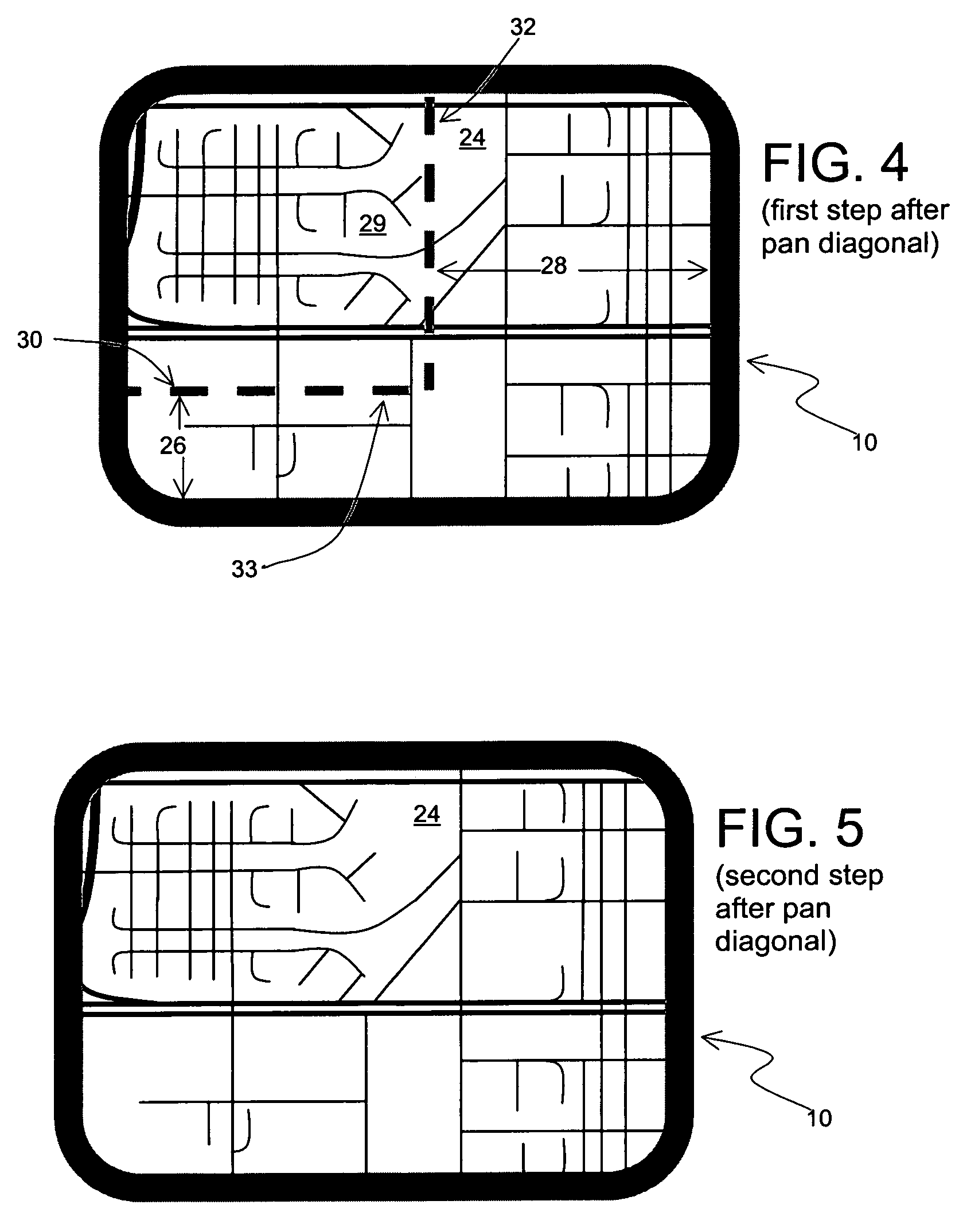
[0030]In this second example, the user starts with the same view 12 as shown in FIG. 1. In this second example, the user pans diagonally, toward the lower right. FIG. 4 shows the transition view on the display screen 10 of the computing platform in the first step after the user performs the operation of panning diagonally toward the lower right. In this case, the new view 24 displays new material on both the bottom 26 and on the right 28 of the screen. On the upper left side 29 of the view 24 on the display screen 10 is a portion of the same material that was visible prior to panning.

[0031]In order to provide visual continuity, a boundary line 30 defining the limits of the old view is rendered on the new view 24. Because the panning operation is diagonal, the boundary line 30 includes a vertical portion 32 extending from the top of the display screen 10 and a horizontal portion 33 extending from the left side of the display screen 10.

[0032]FIG. 5 shows the second step of the visual ...


PUM


Abstract

A method for providing visual continuity when performing a zooming or panning operation with a graphical map shown on display screen of a computing platform. When a user of the computing platform operates the user interface thereof to perform a zooming or panning operation, a first map view of a first geographic area is replaced with a second map view of a second geographic area, such that at least a portion of the first and second geographic areas overlap. In order to provide visual continuity, a transition view is shown on the display screen of the computing platform between the showing of the first map view and the showing of the second map view. The transition view is shown for several seconds immediately after the user operates the user interface to perform the zooming or panning operation. The transition view shows either the first map view or the second map view. The transition view also includes a boundary line that is overlaid on the map view being shown. The boundary line is located on the map view used for the transition view to show the border of the portion of the other map view which is visible in the map view used for the transition view. The method for providing visual continuity is particularly useful for in-vehicle navigation systems or hand-held devices with small display screens. The method can also be applied to text windows.

Description

BACKGROUND OF THE INVENTION[0001]The present invention relates to the presentation of map information on a display screen of a computing device, and more particularly, the present invention relates to a way to improve the presentation of map information on a display screen of a computing device when a user pans or zooms the displayed map.[0002]There are various computing platforms that graphically display maps of geographic areas. For example, some in-vehicle navigation systems include a display screen upon which a map of a geographic area can be displayed graphically. In addition, by using appropriate software applications, maps can also be displayed on general purpose computing platforms, such as personal computers and personal digital assistants.[0003]Some computing platforms and applications that display graphical maps include features that allow a user to interact with the map. Various types of user interaction may be supported. Among these types of user interaction is the abil...

Claims


Application Information

Patent Timeline
Patent Type & Authority Patents(United States)
IPC IPC(8): G09G5/00G01C21/36G06F3/048G09G5/34
CPCG01C21/367G06F3/0481G06F3/0485G09G5/34G06F2203/04806G09G2340/145
Inventor BARTON, MARKKOZAK, FRANK
Owner HERE GLOBAL BV
Why Eureka
Try Eureka