
Adjusting apparatus for a bicycle brake control device

Inactive Publication Date: 2005-10-25
SHIMANO INC
View PDF9 Cites 18 Cited by
  • Summary
  • Abstract
  • Description
  • Claims
  • Application Information

AI Technical Summary

Benefits of technology

[0005]The present invention is directed to various features of a bicycle braking apparatus. In one embodiment, an adjusting apparatus for a bicycle brake control device comprises a brake control member bracket adapted to be mounted to a handlebar and a brake control member movably mounted to the brake control member bracket such that it can move from a brake release position toward a brake operating position. An adjustment member is disposed between the brake control member bracket and the brake control member to adjust an orientation of the brake control member relative to the brake control member bracket when the brake control member is in the brake release position. Additional inventive features will become apparent from the description below, and such features may be combined with the above features to provide additional benefits.

Problems solved by technology

As a result, when the rider's hand is small, the tip of the lever member can be located too far from the handlebar for the rider to reach easily.

Method used


Image

  • Adjusting apparatus for a bicycle brake control device
  • Adjusting apparatus for a bicycle brake control device
  • Adjusting apparatus for a bicycle brake control device

Examples


Embodiment Construction

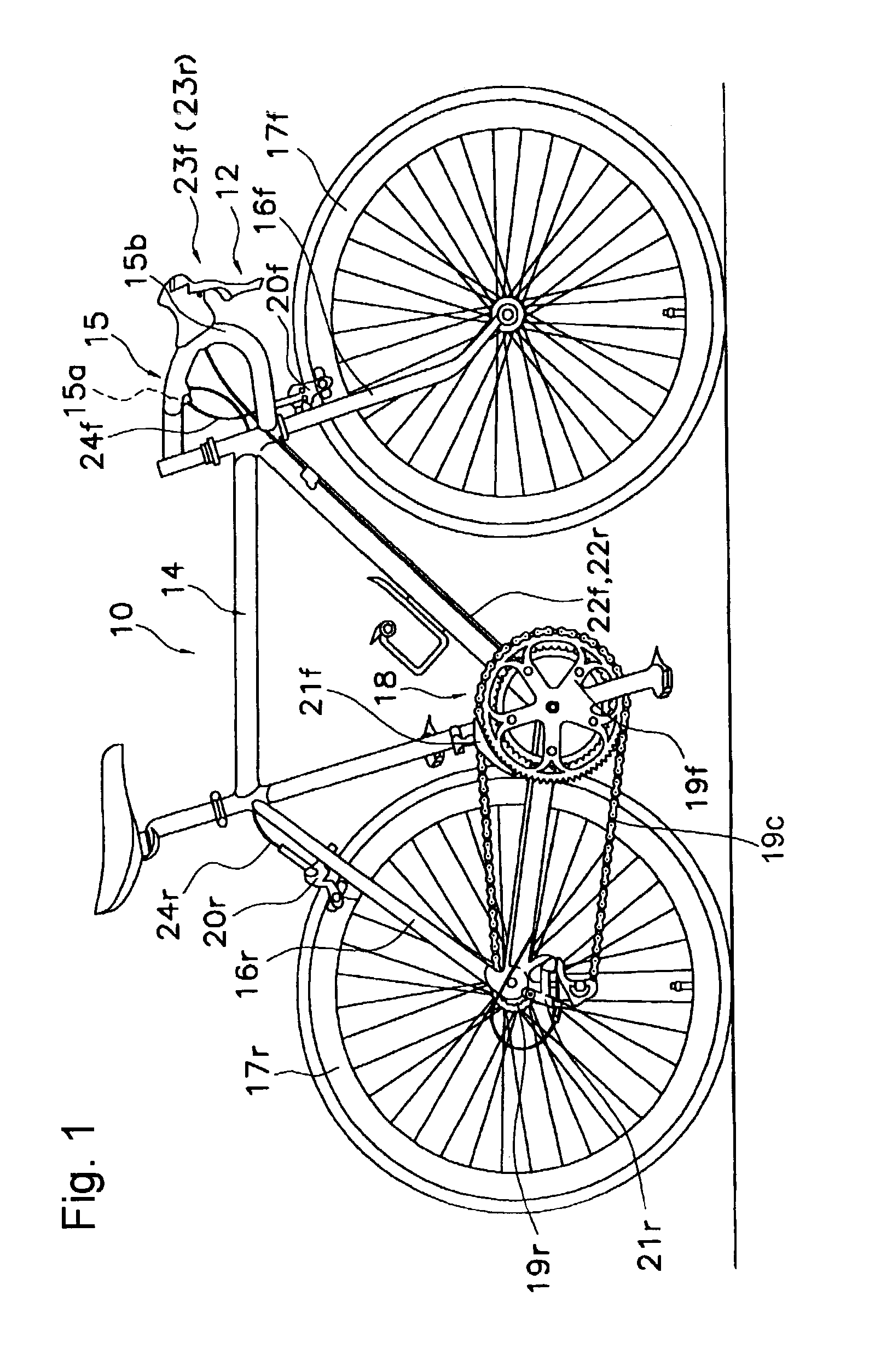
[0014]FIG. 1 is a side view of a particular embodiment of a bicycle 10 that may include one or more embodiments of an adjusting apparatus for a brake control device. The general technology for this bicycle 10 is in the public domain, so a detailed description of the bicycle's constituent parts will be omitted.

[0015]The bicycle 10 is a conventional road racer-type bicycle, and it includes a bicycle frame 14 having a handlebar 15, front and rear forks 16f and 16r, front and rear wheels 17f and 17r, a drive apparatus 18 that includes front and rear sprockets 19f and 19r, a chain 19c front and rear derailleurs 21f and 21r, and a brake system 12.

[0016]The handlebar 15 is a general drop-type handlebar, and has a center area 15a that extends left and right in directions essentially perpendicular to the bicycle's direction of motion, as well as a pair of curved areas 15b that are curved at either end of the center area 15a such that the peak of each curve faces away from the front of the bi...


PUM


Abstract

An adjusting apparatus for a bicycle brake control device comprises a brake control member bracket adapted to be mounted to a handlebar and a brake control member movably mounted to the brake control member bracket such that it can move from a brake release position toward a brake operating position. An adjustment member is disposed between the brake control member bracket and the brake control member to adjust an orientation of the brake control member relative to the brake control member bracket when the brake control member is in the brake release position.

Description

BACKGROUND OF THE INVENTION[0001]The present invention is directed to bicycles and, more particularly, to various features of a bicycle braking apparatus.[0002]Brake control devices that operate brake mechanisms usually are mounted to the handlebar of a bicycle. A brake control device usually comprises a mounting bracket that is mounted to the handlebar and a lever member that is movably mounted to the mounting bracket. The lever member is mounted such that it can move from a brake release position toward the handlebar. Unless they are opposite levers, lever members are disposed such that, irrespective of the handlebar configuration, the tips thereof open toward the ends of the handlebar. The lever member is connected to the brake mechanism via a brake wire or a hydraulic apparatus, and normally pressure is constantly applied to the lever member in the direction of the brake release position. The rider applies the brake by grasping the tip of the lever member using his or her finger...

Claims


Application Information

Patent Timeline
IPC IPC(8): B62L3/00B62K23/00B62K23/06B62L3/02
CPCB62K23/06B62L3/02Y10T74/20438
Inventor IRIE, YOSHINORISHIRAISHI, HIROAKISHAHANA, SATOSHI
Owner SHIMANO INC
Features
  • Generate Ideas
  • Intellectual Property
  • Life Sciences
  • Materials
  • Tech Scout
  • Unparalleled Data Quality
  • Higher Quality Content
  • 60% Fewer Hallucinations
Learn More