
Parachute active protection apparatus

a protection apparatus and parachute technology, applied in the field of parachute active protection apparatus, can solve the problems of limiting the transportability and maneuverability of the protected vehicle, the inability of most other military vehicles to survive a direct hit from an rpg, and the use of rocket propelled grenades by enemy forces

Inactive Publication Date: 2005-10-25
US ARMY AS REPRESENTED BY THE SEC OF THE ARMY
View PDF7 Cites 86 Cited by
  • Summary
  • Abstract
  • Description
  • Claims
  • Application Information

AI Technical Summary

Benefits of technology

"The invention is a countermeasure for rocket propelled grenades (RPGs) that can be used to protect vehicles and personnel from damage caused by these grenades. The invention involves deploying a parachute in the flight path of an incoming RPG to damage, disturb, or cause premature detonation of the grenade. The invention uses a tracking apparatus to detect the RPG and a firing solution computer to determine the proper time to launch the countermeasure. The invention is simple, lightweight, and can be easily integrated into existing vehicles and structures. Overall, the invention provides a simple and effective way to protect against RPGs."

Problems solved by technology

Rocket propelled grenades, used by enemy forces, pose a serious threat to U.S. military vehicles and personnel.
Most other military vehicles, however, cannot survive a direct hit from an RPG.
This additional armor is heavy and voluminous and consequently limits the transportability and maneuverability of the protected vehicle.
Also, such armor engages the incoming RPG very close to the exterior of the vehicle where the RPG may still cause significant damage to the vehicle, its' occupants, and adjacent personnel.
The main disadvantages of such a system are the precise timing required for achieving a successful intercept, and the possibility of the explosive counter munitions causing damage to the protected vehicle and personnel.

Method used


Image

  • Parachute active protection apparatus
  • Parachute active protection apparatus
  • Parachute active protection apparatus

Examples


Embodiment Construction

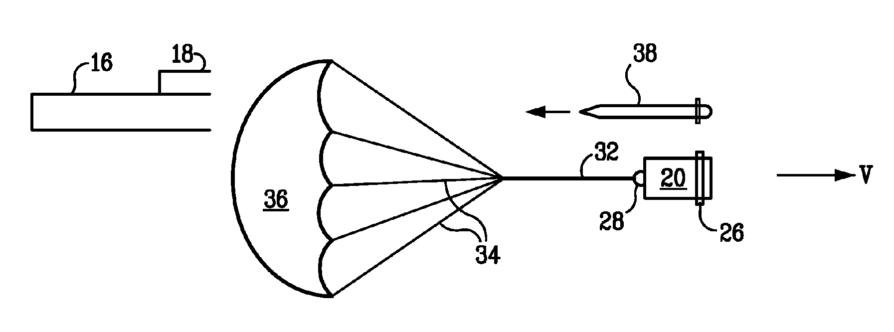
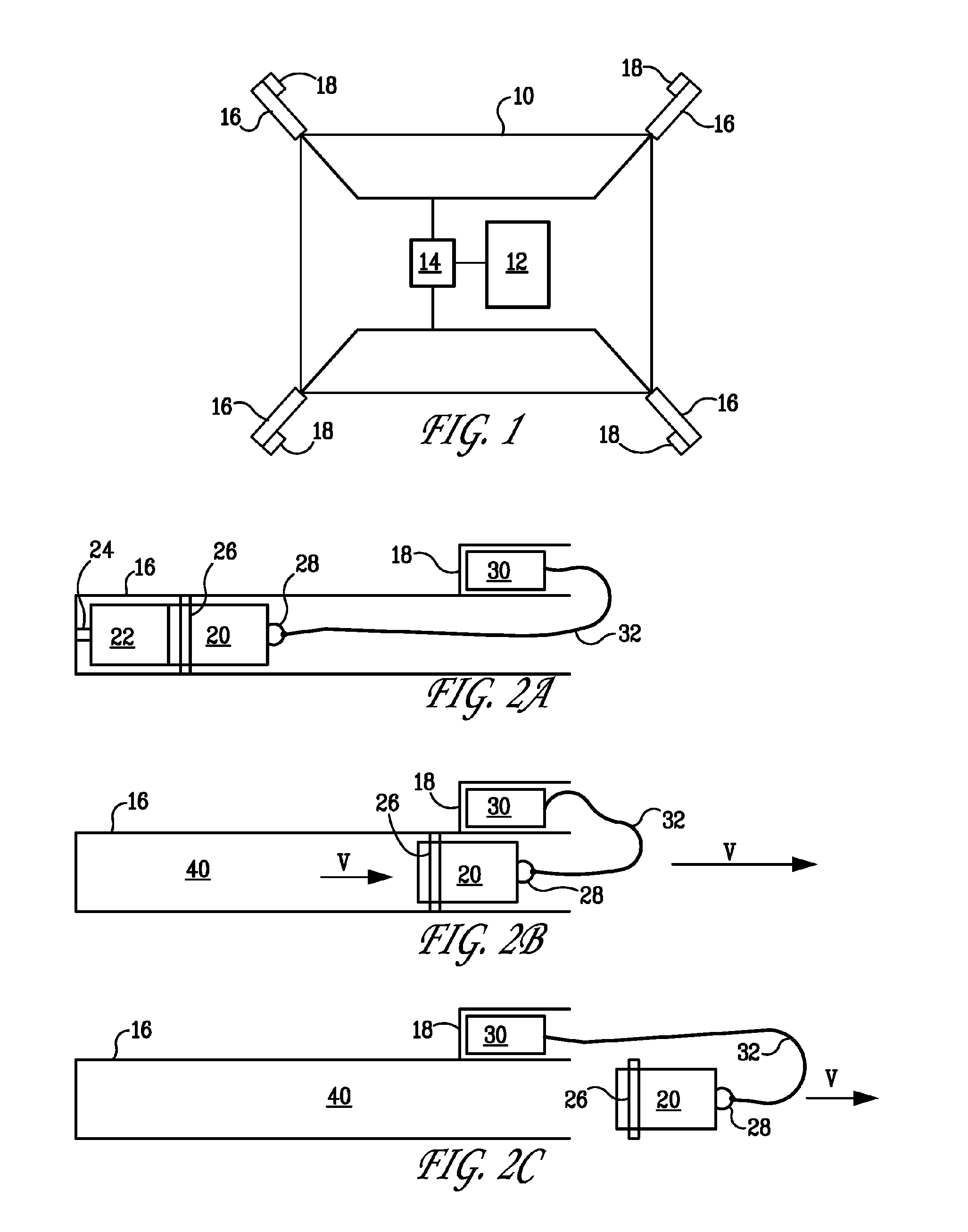
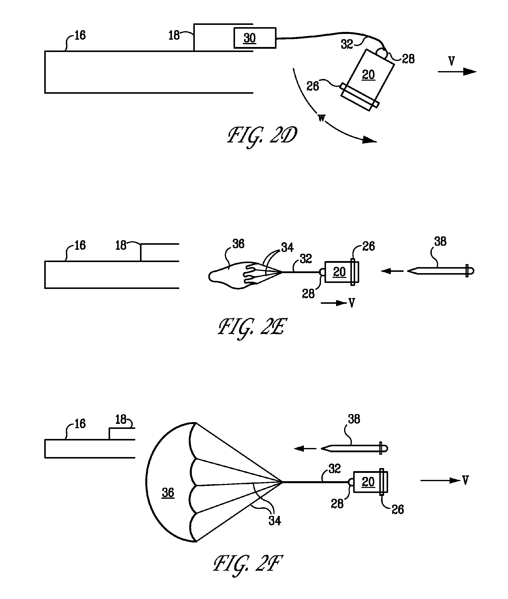
[0011]A purpose of the present invention is to damage, disturb or cause premature detonation of an incoming RPG by deploying a parachute into its flight path. An array of launchers (similar to the M6 discharger found on U.S. combat vehicles), pointing in different directions, are affixed to an object to be protected. The object to be protected may be a vehicle or a stationary structure such as a building. The invention uses a known apparatus for tracking the incoming RPG. Such apparatus are capable of tracking incoming projectiles using radar and determining the incoming projectile's velocity and flight path direction. This information is then used by a firing solution computer to calculate the optimum time to launch the countermeasure and to determine from which tube it should be launched.

[0012]FIG. 1 is a schematic drawing of the invention. An object 10 to be protected may be a vehicle or a stationary structure such as a building. Mounted on the object 10 is a tracking apparatus 1...


PUM


Abstract

An apparatus for protecting an object from an incoming munition includes a tracking apparatus mounted on the object, for tracking the incoming munition; a firing solution computer connected to the tracking apparatus; a plurality of launch tubes mounted on the object, the plurality of launch tubes pointing in different directions so as to maximize coverage of an area surrounding the object; a parachute container attached to each launch tube; an igniter disposed in a rear of each launch tube and connected to the firing solution computer; a propelling charge disposed in front of each igniter; a mass disposed in front of each propelling charge; a connecting ring attached to a front of each mass; a parachute disposed in the parachute container; and a cable connecting the connecting ring and the parachute.

Description

CROSS REFERENCE TO RELATED APPLICATIONS[0001]This application claims benefit under 35 USC 199(e) of provisional application 60 / 521,453, filed Apr. 28, 2004, the entire file wrapper contents of which provisional application are herein incorporated by reference as though fully set forth at length.STATEMENT OF GOVERNMENT INTEREST[0002]The inventions described herein may be manufactured, used and licensed by or for the U.S. Government for U.S. Government purposes.BACKGROUND OF THE INVENTION[0003]The invention relates in general to munitions and in particular to countermeasures for rocket propelled grenades (RPG).[0004]Rocket propelled grenades, used by enemy forces, pose a serious threat to U.S. military vehicles and personnel. Heavily armored vehicles, such as the Abrams tank and the Bradley Fighting Vehicle, are equipped with advanced armors to defeat the RPG's shaped charge warhead. Most other military vehicles, however, cannot survive a direct hit from an RPG.[0005]An existing appro...

Claims


Application Information

Patent Timeline
Patent Type & Authority Patents(United States)
IPC IPC(8): B64D1/00B64D1/04B64D7/00F41H5/007F41H11/02F42B12/66
CPCB64D7/00F41H5/007F41H11/02F42B12/66F41H13/0006
Inventor KOENIG, WALTER H.MALEJKO, GREGORYGRAU, JOHN C.
Owner US ARMY AS REPRESENTED BY THE SEC OF THE ARMY
Learn More