Plug connector housing with locking mechanism and plug connector having such housing

a technology of locking mechanism and plug connector, which is applied in the direction of electrical equipment, connection, coupling device connection, etc., can solve the problems of increasing the size of the connector, difficulty or impossible to unlock, so as to reduce the force required for unlocking and unlocking. , the effect of reducing the force required

Active Publication Date: 2005-10-25
JST MFG CO LTD
View PDF8 Cites 4 Cited by
  • Summary
  • Abstract
  • Description
  • Claims
  • Application Information

AI Technical Summary

Benefits of technology

[0009]The present invention was made in view of the above-mentioned points, and objects of the invention are to provide a plug connector housing with a locking mechanism of the above-mentioned general type, wherein the lock arms and the control arms are extended opposite one another in the depth direction on both sides in the width direction of the housing to reconcile making the plug connector and the receptacle connector thinner and more compact, making the unlocking and withdrawal operations easier and reducing the forces required for unlocking with each other. A further object of the invention is to provide a plug connector with a locking mechanism using such a plug connector housing.

Problems solved by technology

However, when the former measure is taken, the connectors will get larger in size, contrary to the efforts of making the connectors more compact.
When the latter measure is taken, the tongue or the finger-pressing part is brought closer to the counterpart jack connector or socket, which makes it very difficult or impossible to unlock by pressing the tongues or the finger-pressing parts with one's fingers when the counterpart jack connector or socket is mounted in a narrow space leaving only a tight work space.
When the unlocking arms are extended toward the front of the plug connector for the same purpose, it will pose a problem that it is very difficult or impossible to unlock by pressing the unlocking arms with one's fingers when the counterpart receptacle connector is mounted in a narrow space with a tight working space.
Moreover, as the fitting part of the locking piece fits with the fitting part of the receptacle connector by being displaced in the thickness direction of the plug connector, this detracts from the efforts of reducing the plug connector and the receptacle connector in thickness.

Method used


Image

  • Plug connector housing with locking mechanism and plug connector having such housing
  • Plug connector housing with locking mechanism and plug connector having such housing
  • Plug connector housing with locking mechanism and plug connector having such housing

Examples


Embodiment Construction

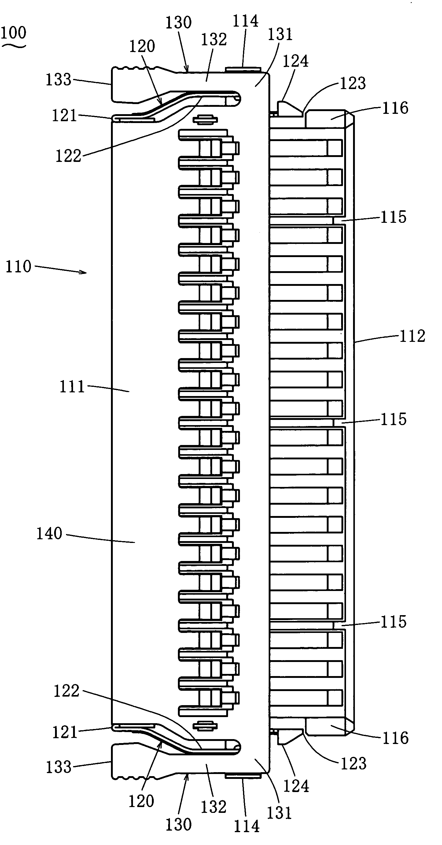
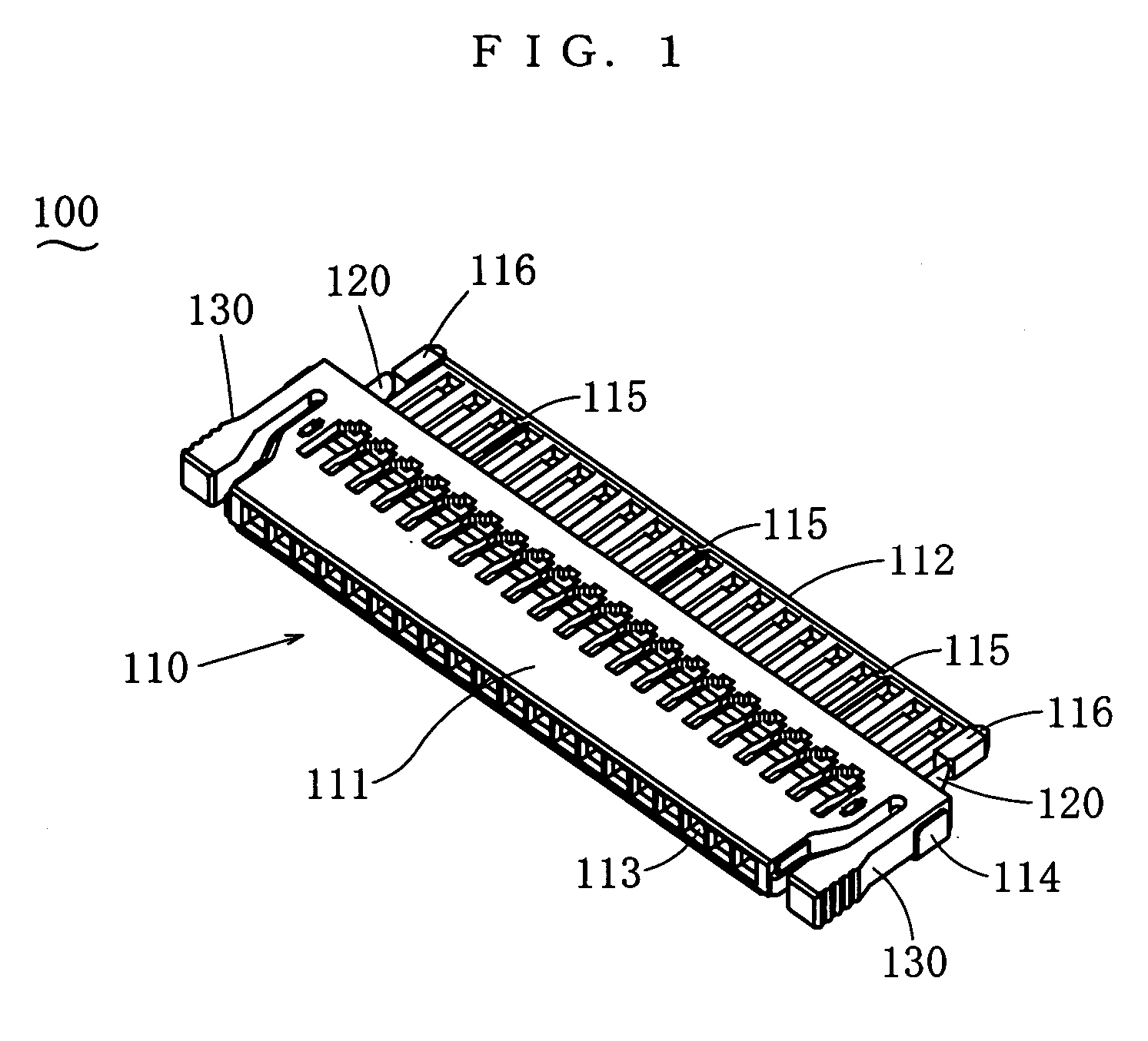
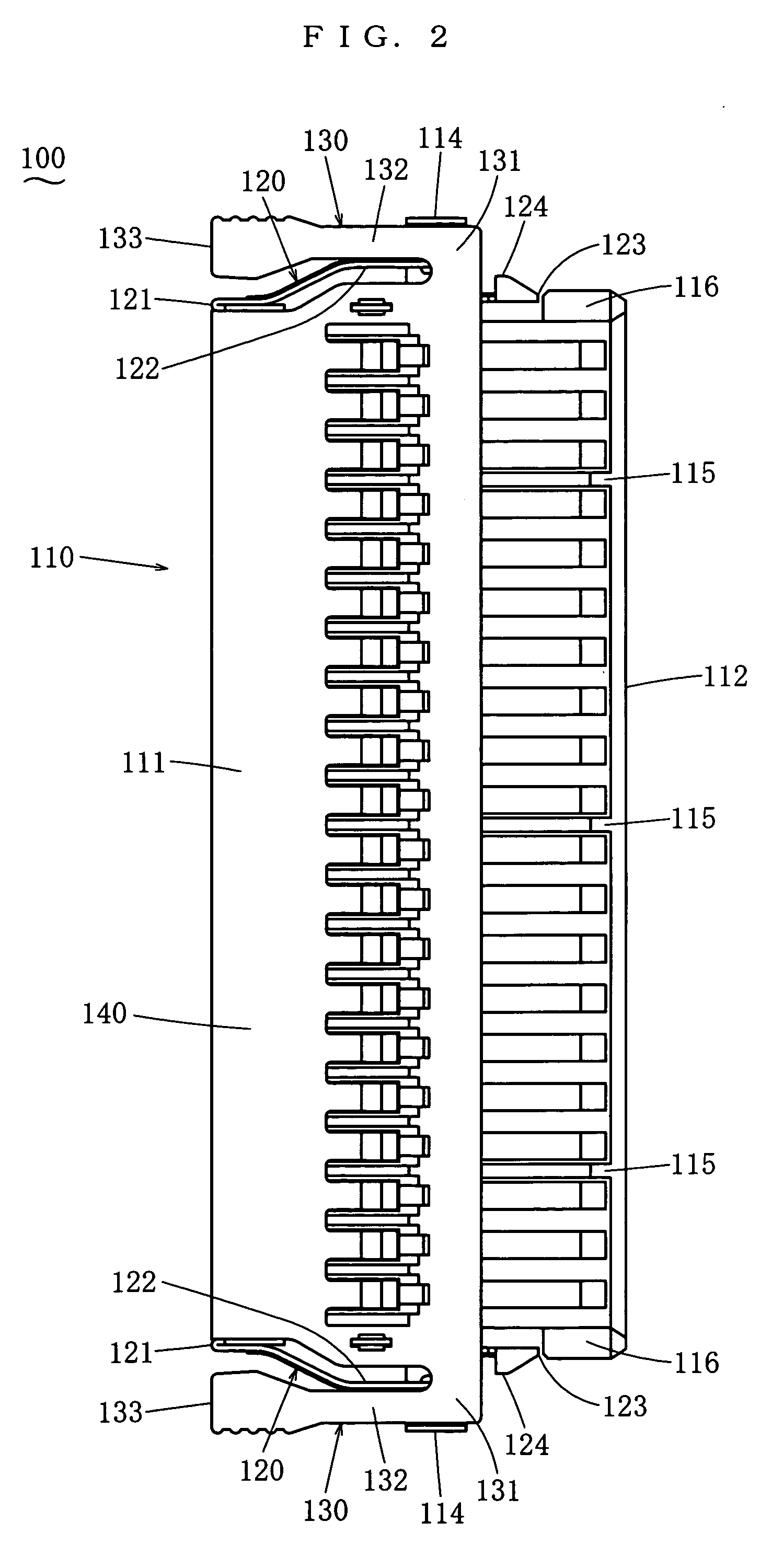
[0031]In the following an embodiment of the present invention will be described. FIG. 1 through FIG. 5 show a plug connector housing with locking mechanism 100 being an embodiment of the present invention. FIG. 7 and FIG. 8 show a plug connector with locking mechanism PC comprising the plug connector housing with locking mechanism 100 and plug-connector-side contacts 200 (refer to FIG. 6) to be inserted therein. This plug connector with locking mechanism PC is to be inserted into or withdrawn from a receptacle connector RC shown in FIG. 10 through FIG. 13. In the case of this embodiment, the plug connector with locking mechanism PC is connected to electric wires W being independent discrete lines, and the receptacle connector RC is mounted on a printed circuit board B being a liquid crystal panel. The plug connector with locking mechanism according to the present invention, however, is not limited in any way by this embodiment with regard to what may be connected to it. Moreover, th...


PUM


Abstract

A plug connector with a locking mechanism includes a housing having a body and an inserting part, a contact received therein, lock arms provided on both sides in a width direction of the housing and extending rearward in a depth direction and having protrusions provided at top ends thereof, and control arms provided on both sides in the width direction of the housing and extending forwardly in the depth direction. The control arms transmit forces working inwardly in the width direction to the lock arms. The control arms are arranged in such a way that when the inserting part is inserted into the cavity of the receptacle connector, the protrusions will be caught on the catching faces of the receptacle connector, and when the top ends of the control arms are pressed inwardly in the width direction, the protrusions will be released from the catching faces.

Description

BACKGROUND OF THE INVENTION[0001]1. Field of the Invention[0002]The present invention relates to a plug connector with a locking mechanism, which will be locked in a receptacle connector when it is inserted into the receptacle connector and can be withdrawn out of the receptacle connector when an unlocking operating is performed on the plug connector. The invention further relates to a plug connector housing with a locking mechanism as a component thereof.[0003]2. Related Art[0004]Japanese Patent Publication 3094668 discloses a connector with a locking mechanism comprising a plug connector, a molded cover enclosing the plug connector, lock levers cantilevered respectively on the inward faces of both side walls in the width direction of a cover body constituting the molded cover, and a jack connector corresponding to the plug connector. The connectors are locked together or unlocked by fitting or releasing hooks provided on the other ends of the lock levers and fitting parts provided...

Claims


Application Information

Patent Timeline
Patent Type & Authority Patents(United States)
IPC IPC(8): H01R13/627H01R13/629
CPCH01R13/6275H01R12/727H01R12/79H01R13/629
Inventor KURODA, KEIJIARAMOTO, KIYOSHIMORIWAKE, RYO
Owner JST MFG CO LTD
Why Eureka
Try Eureka