Rubber made canister and manufacture method of the same

A manufacturing method and rubber technology, which is applied to gas shock absorbers, elastic couplings, mechanical equipment, etc., can solve the problems of diameter expansion obstruction, time-consuming and labor-intensive configuration, and increased ply cut-off loss, etc., to achieve compact thickness, Improved durability and stable performance

Inactive Publication Date: 2007-03-28
TOYO TIRE & RUBBER CO LTD
View PDF2 Cites 3 Cited by
  • Summary
  • Abstract
  • Description
  • Claims
  • Application Information

AI Technical Summary

Problems solved by technology

[0005] However, in order to interpose a wide ply between the inner rubber and the outer rubber to form a reinforcing ply, the following steps are required: a process of manufacturing a wide ply in advance; The process of placing the bead on the outside of the end; the process of folding back the end of the carcass and locking it on the bead, so it is easy to increase the manufacturing process and man-hours of the rubber cylinder
[0006] In addition, in the case of adopting the above-mentioned configuration, expensive equipment is required for the manufacture of the carcass and the folding of the end of the carcass, and when a variety of rubber cylinders with different lengths and diameters are manufactured in small batches, the carcass The cut-off loss becomes larger, and the manufacturing cost of the rubber cylinder becomes higher
In addition, the weft of the carcass may hinder the diameter expansion during vulcanization molding, which may cause the performance of the rubber cylinder to be unstable.
[0007] Furthermore, in the above-mentioned method of embedding the bead, the method of forming the ring-shaped bead in advance is adopted, and since the ring-shaped bead is covered with unvulcanized rubber, the arrangement is time-consuming and labor-intensive.
Moreover, the method of winding thinner wires multiple times is time-consuming and labor-intensive.

Method used


Image

  • Rubber made canister and manufacture method of the same
  • Rubber made canister and manufacture method of the same
  • Rubber made canister and manufacture method of the same

Examples


no. 1 approach

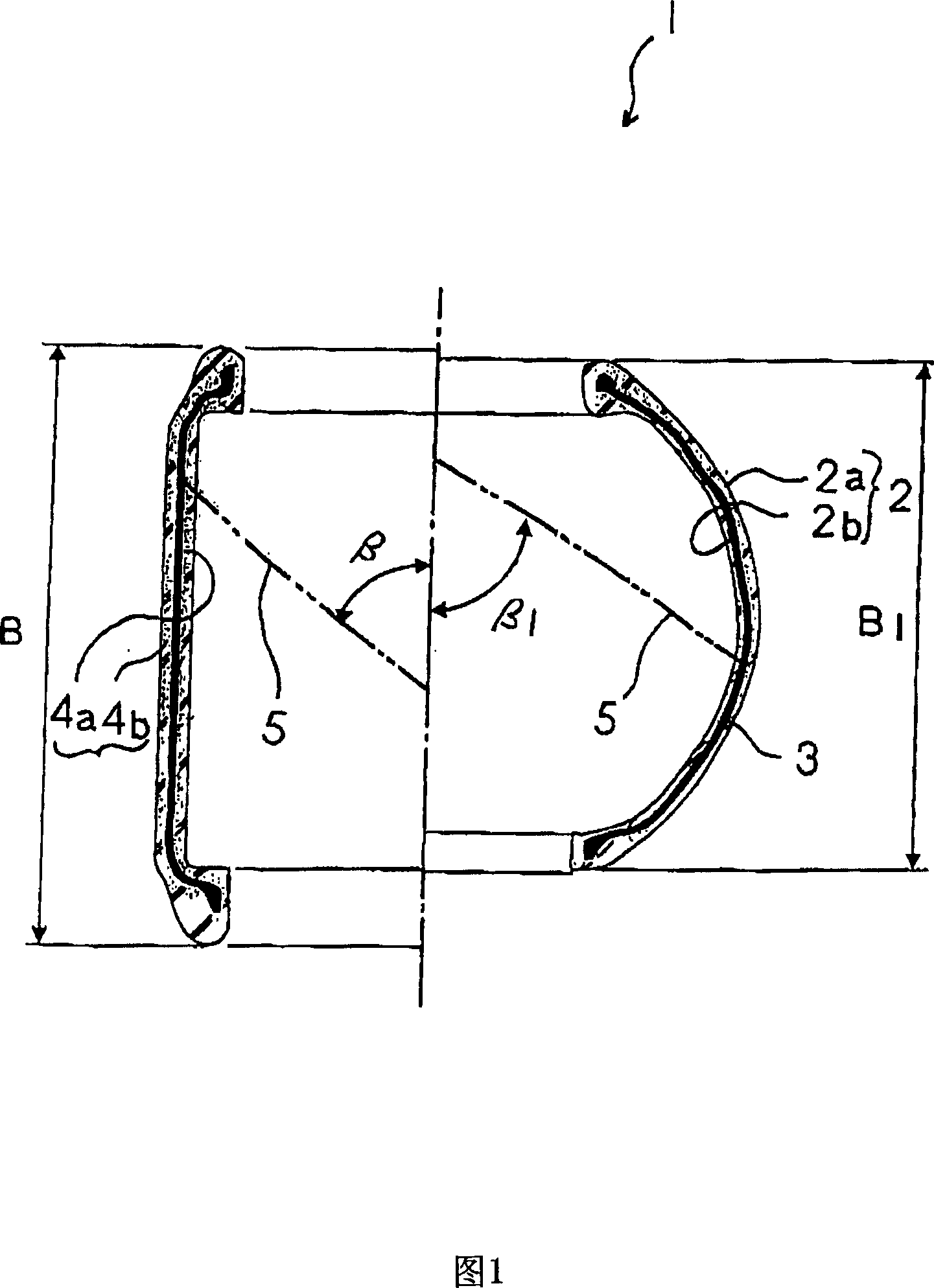
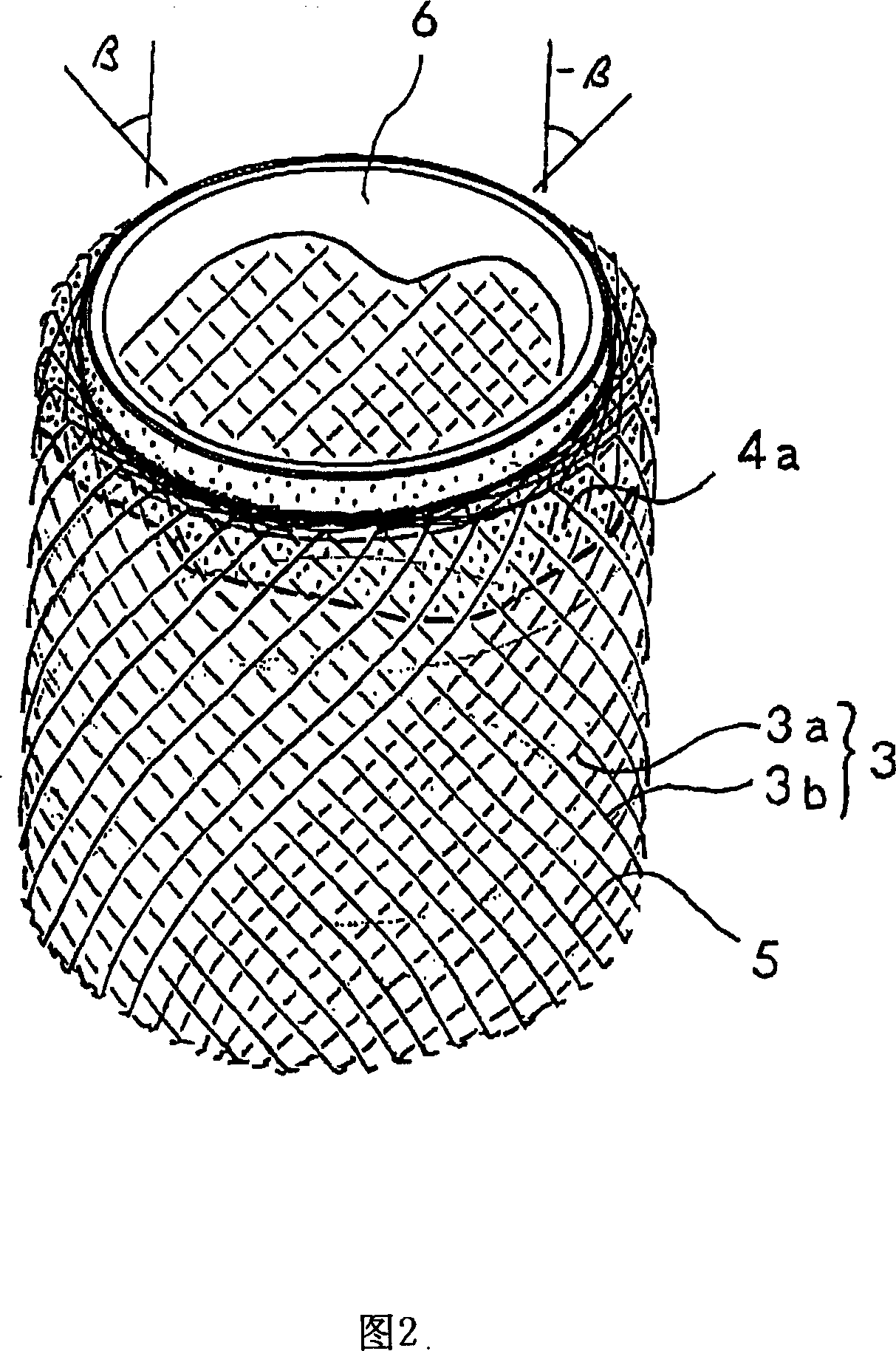
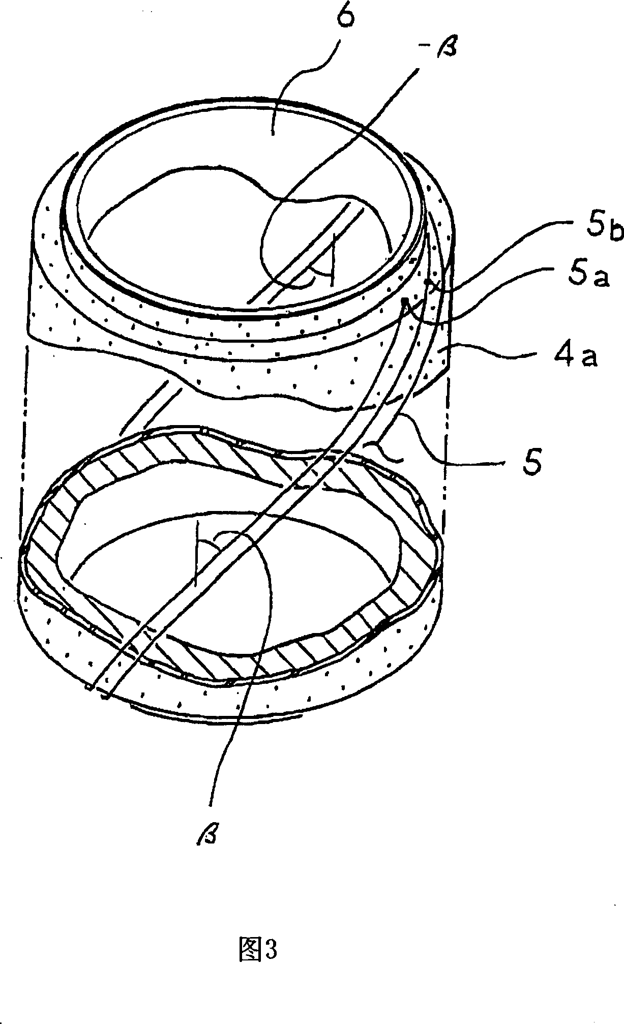
[0079]1 is a cross-sectional view of a rubber cylinder according to a first embodiment of the present invention. The left half shows the state before vulcanization molding, and the right half shows the state after vulcanization molding. Fig. 2 is a perspective view showing a reinforcing ply, showing a state formed on the outside of the unvulcanized rubber on the inner surface of the mold and the forming mold. In addition, in FIG. 2, only the upper part of the molding die and the unvulcanized rubber on the inner surface are illustrated.

[0080] The rubber cylinder 1 of the first embodiment is, for example, a member for fixing fittings at both ends to serve as a diaphragm of an air spring, and has a structure in which the diameter at the center is larger than the diameter at both ends and as a whole The cylindrical rubber membrane 2 having a substantially spherical shape is provided with a reinforcing ply 3 for increasing resistance to internal pressure and transmission force.

[0...

no. 2 approach

[0110] 10 is a cross-sectional view of a rubber cylinder according to a second embodiment of the present invention. The left half shows the state before vulcanization molding, and the right half shows the state after vulcanization molding. Fig. 11 is a side view of the linear member, and the left end shows an axial cross-sectional view. Fig. 12 is a transverse cross-sectional view of the linear member. Fig. 13 is a schematic diagram showing the connection of both ends of the linear member, (a) shows the state before connection, and (b) shows the state after connection.

[0111] The rubber cylinder 11 of the second embodiment is used, for example, as a diaphragm of a piston-type air spring mounted on a truck or a bus. The upper end is sandwiched by a pair of connecting fittings 12a, 12b, and the lower end is press-fitted. The insertion portion 13a of the piston 13. Although the structure of this rubber-made cylinder 11 is substantially the same as the rubber-made cylinder 1 of 1st ...

no. 3 approach

[0150] 21 is a cross-sectional view of a rubber cylinder according to a third embodiment of the present invention. The left half shows the state before vulcanization molding, and the right half shows the state after vulcanization molding. Fig. 22 is a perspective view showing the reinforcing ply, and the illustration of the rubber film thereof is omitted.

[0151] The rubber cylinder 25 of the third embodiment is, for example, a member used as a diaphragm of an air spring, and has almost the same structure as the rubber cylinder 1 of the first embodiment, but a pair of fittings 26 are integrally fixed at both ends , 27, and constitute a rubber cylinder 28 with fittings.

[0152] As in the first embodiment, the reinforcing cord layer 3 is composed of a single reinforcing cord 5 surrounding the central axis of the rubber tube 25. The one reinforcing cord 5 is wrapped around the fittings 26, 27, and the hooking portion 5c of the reinforcing cord 5 is hooked on the peripheral edge of ...


PUM


Abstract

The present invention provides a rubber cylinders with stability performance which can reduce the number of the manufacturing process, the working hours, and the manufacturing cost. One reinforcing cord 5 is embedded in a cylinder rubber membrane 2 in a mode of enclosing a center axes. The reinforcing cord 5 passes through both ends of the cylinder rubber membrane 2 and inclines at a definite angle of inclination relative the center axes. The enclosement operation of the reinforcing cord 5 is repeated. By such constitution, the reinforcing cord 5 is arranged in the peripheral direction with a certain gap in the circumferential direction and its arrangement positions cincture the center axes for a circle. The reinforcing cord 5 is arranged on the whole periphery to form two cylindrical reinforcing cord layers, wherein the inclination directions of the reinforcing cord 5 cross mutually.

Description

Technical field [0001] The present invention relates to, for example, a rubber cylinder used as a diaphragm of an air spring, and a method for manufacturing the rubber cylinder. Background technique [0002] Generally, an air spring installed in a railway vehicle, a truck, a bus, or the like has a structure in which a pair of fittings are fixed to both ends of a rubber cylinder as a diaphragm. A reinforced ply for pressure-resistant reinforcement is embedded in the rubber cylinder, and a ring-shaped crimp for reinforcing the end is embedded (for example, Japanese Patent Office JP 2001-20148 Bulletin, JP 2003- 202045 Bulletin). [0003] The reinforcing ply is formed by sandwiching a wide ply between the inner rubber and the outer rubber, and the two obliquely cut plies are arranged to overlap and overlap each other in the offset direction, thereby forming Double-layer reinforced ply. The wide ply is formed by connecting a plurality of reinforcing cords arranged in parallel with we...

Claims


Application Information

Patent Timeline
Patent Type & Authority Applications(China)
IPC IPC(8): F16F9/04F16D3/50B21F15/04
Inventor 横堀志津雄押方满男上坪一晴
Owner TOYO TIRE & RUBBER CO LTD
Why Eureka
Try Eureka