Finishing wheel holding mechanism for gear finishing apparatus

a technology of holding mechanism and finishing wheel, which is applied in the direction of gear teeth, manufacturing tools, gear-teeth manufacturing apparatus, etc., can solve the problems of time and labor consumed in fastening the fixing bolts that remain unsolved, and the apparatus has to be suspended from operation, so as to achieve convenient insertion, accurate centering, and simple operation

Inactive Publication Date: 2005-10-25
KANZAKI KOKYUKOKI MFG
View PDF7 Cites 11 Cited by
  • Summary
  • Abstract
  • Description
  • Claims
  • Application Information

AI Technical Summary

Benefits of technology

[0024]According to Invention 1, the finishing wheel holder supported by the base portion of the gear finishing apparatus and rotated within the opening portion of the head frame is provided with a support gear which has an open end portion for finishing wheel insertion and an accepting portion for accepting in a fixed position the finishing wheel inserted through the open end portion; an annular shifting body which is supported slidablly by the internal peripheral portion of the support gear in the open end portion; a projection protruding in the support gear so as to serve as a stopper in contact with the insertion side end face of the finishing wheel; a pressing collar which is inserted, after the finishing wheel is inserted, along the internal circumferential surface of the shifting body to be engaged in a locked state against coming off, and is pushed by the sliding of the shifting body toward the finishing wheel to come into contact with the end face of the finishing wheel to fix the finishing wheel; and an actuator for driving the shifting body toward the accepting portion. Therefore, by operating the actuator, the shifting body driven by the actuator pushes the pressing collar to bring it into contact with the end face of the finishing wheel and there by fixes the finishing wheel. Accordingly, manipulation to operate the actuator permits simple and quick fitting or replacement of the finishing wheel.
[0025]According to Invention 2, as the actuator which is a hydraulic drive unit causes working fluid from the pressure portion to work on the shifting body in the concave through the oil passage and thereby moves it toward the accepting portion of the support gear, the shifting body can be hydraulically driven by the operation of the actuator, resulting in very simple and quick operation.
[0027]According to Invention 4, as the pressing portion is provided with a female-threaded hole disposed in the support gear and reaching the piston and a male-threaded bolt screwed into the female-threaded hole, the actuator can be operated by a simple manipulation of turning the male-threaded bolt. Further, as the hydraulic drive unit is accommodated in the support gear, there is no need to connect any oil passage from outside to rotating parts, enabling reliable operation to be achieved with a simple structure.
[0028]According to Invention 5, whether or not the finishing wheel is fixed can be judged by the extent of protrusion of the rod-shaped indicator fitted to the indicative piston mechanism connected with the active piston mechanism, and reliable operation is thereby ensured.
[0029]According to Invention 6, the finishing wheel is accurately centered by the centering balls accepted into the intermediate member. Further, as the bottom face of the annular recess for accepting the intermediate member is slightly tapered from the open end portion of the support gear toward the accepting portion, the centering balls come into increasingly strong contact with the finishing wheel as the finishing wheel is inserted deeper into the accepting portion. Therefore the finishing wheel can be readily inserted, and accurate centering can be accomplished by the completion of the insertion.
[0030]According to Invention 7, compressed air supplied from the port via the air passage slides the intermediate member in the annular recess, and the shifting body is thereby pushed toward the open end portion of the support gear. Therefore, the finishing wheel, fixed until then by the sliding of the intermediate member, is released from the fixation by the simple operation of supplying compressed air to the port, and can be easily taken out.

Problems solved by technology

Therefore, the apparatus has to be suspended from operation every time the finishing wheel has worn out and needs to be replaced with a new one.
Although the latter finishing wheel holding mechanism permits prompt resumption of finish processing because a new, already positionally adjusted finishing wheel can be brought to its working position when one of the finishing wheels in use has worn out, the problem of the time and labor consumed in fastening the fixing bolts remains unsolved.
Such problems are not limited to honing but also are commonly encountered in wheel finish processing, such as shaving or the like, using a finishing wheel having internal teeth.

Method used


Image

  • Finishing wheel holding mechanism for gear finishing apparatus
  • Finishing wheel holding mechanism for gear finishing apparatus
  • Finishing wheel holding mechanism for gear finishing apparatus

Examples


Embodiment Construction

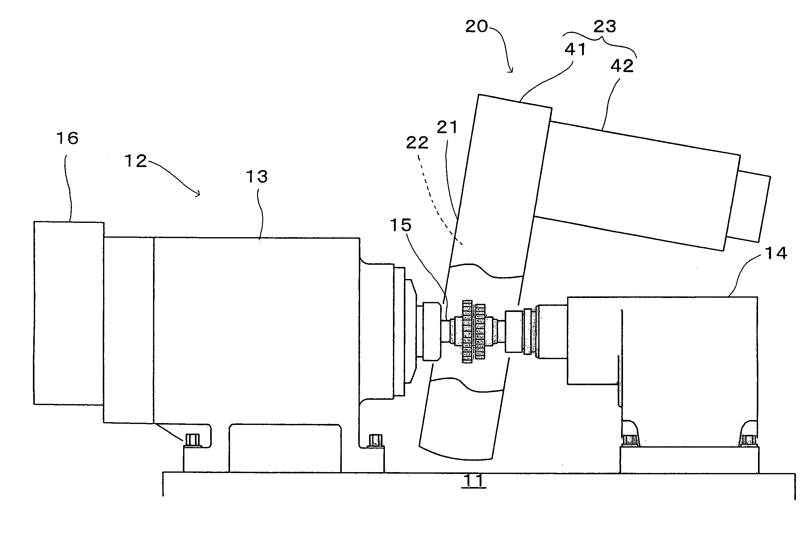
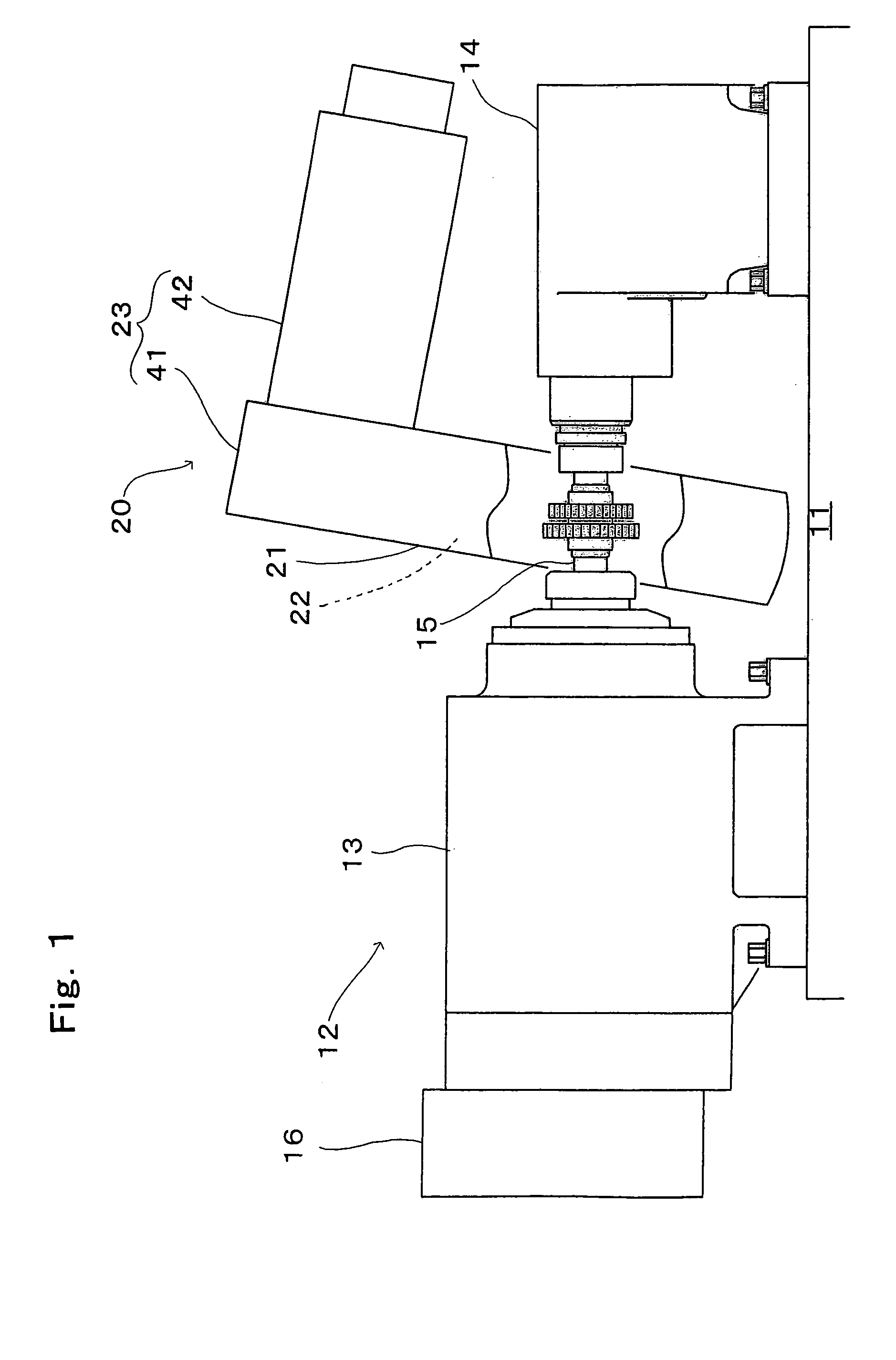
[0040]A preferred embodiment of the present invention will be described below with reference to the accompanying drawings. FIG. 1 shows a partial front view of a gear finishing apparatus provided with a finishing wheel holding mechanism, which is one preferred embodiment of the present invention. The gear finishing apparatus is provided with a table 11 slid by a driving motor (not shown) and a work holder 12 arranged on the table 11. The work holder 12 is provided with two tail stocks 13 and 14 which can slide in parallel to the sliding direction of the table and a motor 16 for driving the shaft 15 of one tail stock 13 to rotate. This causes a work W to be held between the tail stocks 13 and 14 to be rotatable integrally with the shaft 15. Behind the table 11 (deeper beyond the sheet surface of FIG. 1), there is arranged a sliding section (not shown) so supported to be able to approach and retract in a direction substantially perpendicular to the axis of the tail stocks, and a finis...


PUM

PropertyMeasurementUnit
internal diameteraaaaaaaaaa
diameteraaaaaaaaaa
pressureaaaaaaaaaa

Abstract

A finishing wheel holding mechanism for a gear finishing apparatus using a finishing wheel having internal teeth, which permits simple and quick fitting or replacement of a finishing wheel is provided. The finishing wheel holding mechanism comprises a head frame 21 having at the center an opening portion for holding a finishing wheel, and an annular finishing wheel holder portion 22 for fitting finishing wheels A1 (A2), supported rotatablly within the opening portion of the head frame 21; and the finishing wheel holder comprises a support gear 50 having an open end portion 53 for finishing wheel insertion and an accepting portion 54 for fixing the finishing wheel, an annular shifting body 55 within the open end portion 53, a projection 57 contacting the finishing wheel to serve as a stopper, a pressing collar 58 inserted into the shifting body 55 to fix the finishing wheel by sliding the shifting body toward the finishing wheel, and an actuator 60 for driving the shifting body 55 toward the accepting portion.

Description

BACKGROUND OF THE INVENTION[0001]1. Field of the Invention[0002]The present invention relates to a finishing wheel holding mechanism for use in gear finishing apparatuses, such as a honing apparatus and a shaving apparatus, in which a finishing wheel having internal teeth is rotated so as to finish a gear piece in mesh with the finishing wheel.[0003]2. Description of the Related Art[0004]Where a highly accurate tooth profile is required for a gear, finish processing to modify any deformation of the gear having gone through heat treatment, so-called honing, is performed. This finish processing is accomplished by rotating the gear piece to be worked upon in a state in which it is meshed with a finishing wheel having internal teeth at a predetermined crossing angle. The finishing wheel is held by a support gear of a finishing wheel holding mechanism having external peripheral teeth. The support gear is turned by a driving device in mesh with the external peripheral teeth, and is slid b...

Claims


Application Information

Patent Timeline
Patent Type & Authority Patents(United States)
IPC IPC(8): B23F23/00B23F23/12B23F19/00B23F19/05B23F19/06B24B45/00
CPCB23F23/1281Y10T409/108586
Inventor YOSHIOKA, NORIHIROKAWAMOTO, KOJIYAMAGUCHI, MASAAKI
Owner KANZAKI KOKYUKOKI MFG
Why Eureka
Try Eureka