Stator winding structure of a motor or a generator

a technology of winding structure and generator, which is applied in the direction of windings, dynamo-electric components, magnetic circuit shapes/forms/constructions, etc., can solve the problems of increasing coil winding difficulty, increasing winding cost, and increasing the difficulty of coil winding, so as to avoid short circuit

Inactive Publication Date: 2005-10-25
UNIQUE PRODS & DESIGN
View PDF13 Cites 29 Cited by
  • Summary
  • Abstract
  • Description
  • Claims
  • Application Information

AI Technical Summary

Problems solved by technology

In a process of winding, conventional coil conducting wires must be bent for 180 degrees when they come out of a coil slot and go into another coil slot; therefore, the larger the cross-section of the coil wires is, the more the stator electrodes will have, and the harder the winding work will become, and also the lower the slot occupied rate of the wire will be.
For the present, a motor or a generator with collective winding usually has a large cross-section of a coil wire and many stator electrodes, thus increasing difficulty in coil winding and heightening winding cost.
Further, it is hard to bend a coil wire with an excessively large cross-section.
However, the cross-section of a coil wire should be first be taken into consideration in case a motor or a generator needs to output large power, because, when current flows through the coil wire, copper loss caused by resistance will generate extremely high heat energy and the coil wire is likely to be burned to form short circuit and subsequent danger.
Due to difficulty in winding of a coil wire with a large cross-section and high winding cost, a motor or a generator with collective winding is only applicable to equipment or electric carriers with small power output.

Method used


Image

  • Stator winding structure of a motor or a generator
  • Stator winding structure of a motor or a generator
  • Stator winding structure of a motor or a generator

Examples


Embodiment Construction

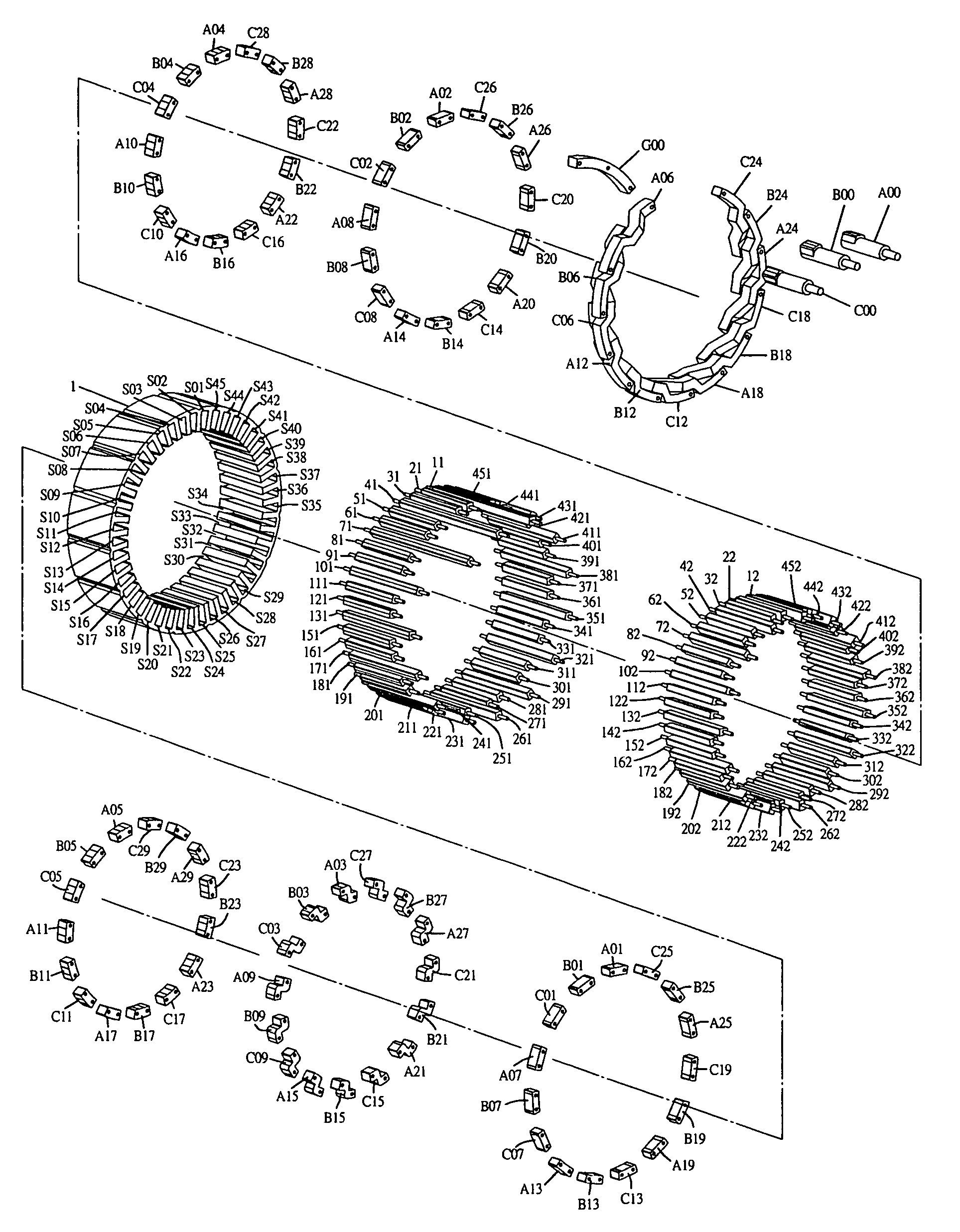
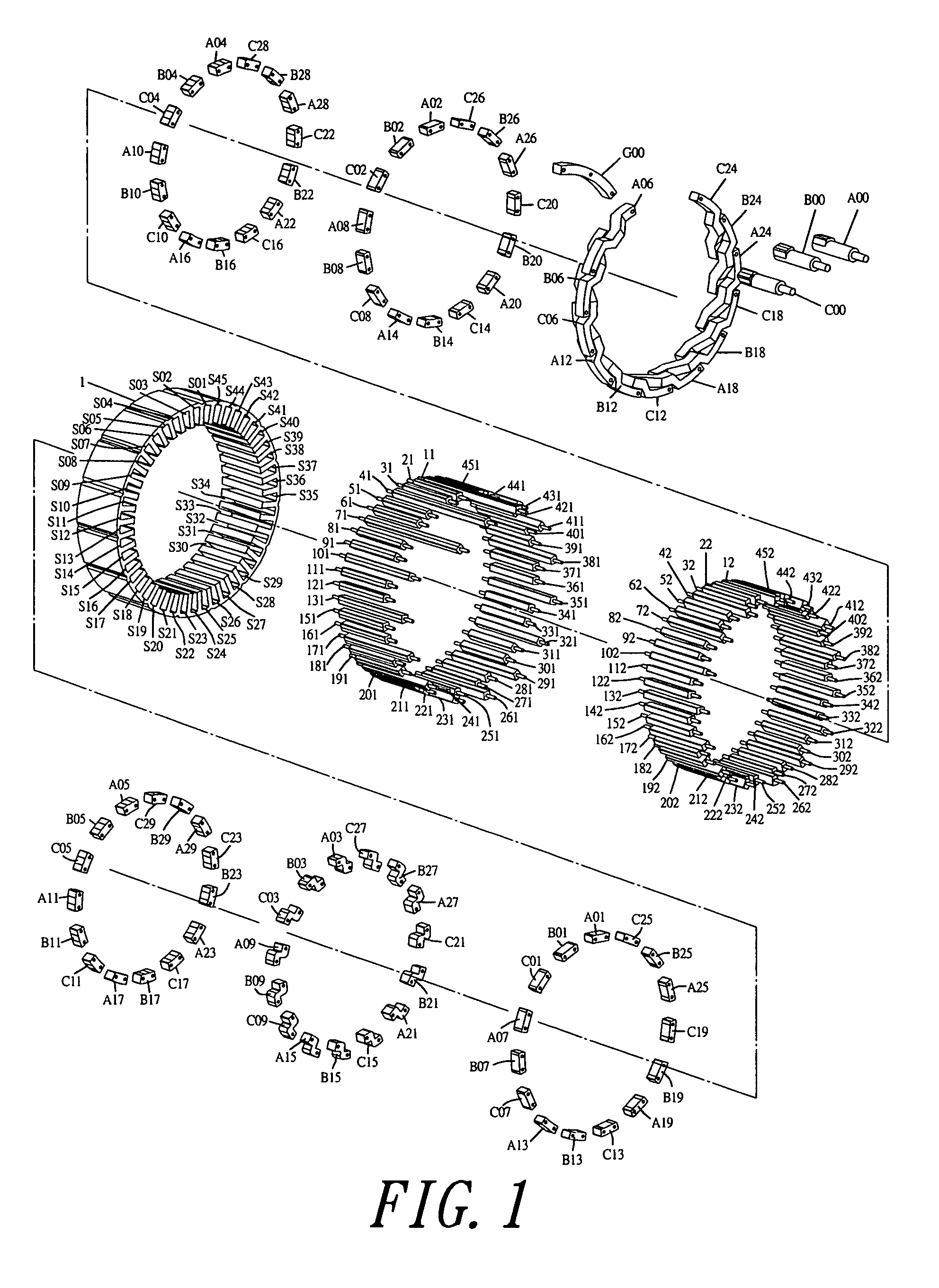
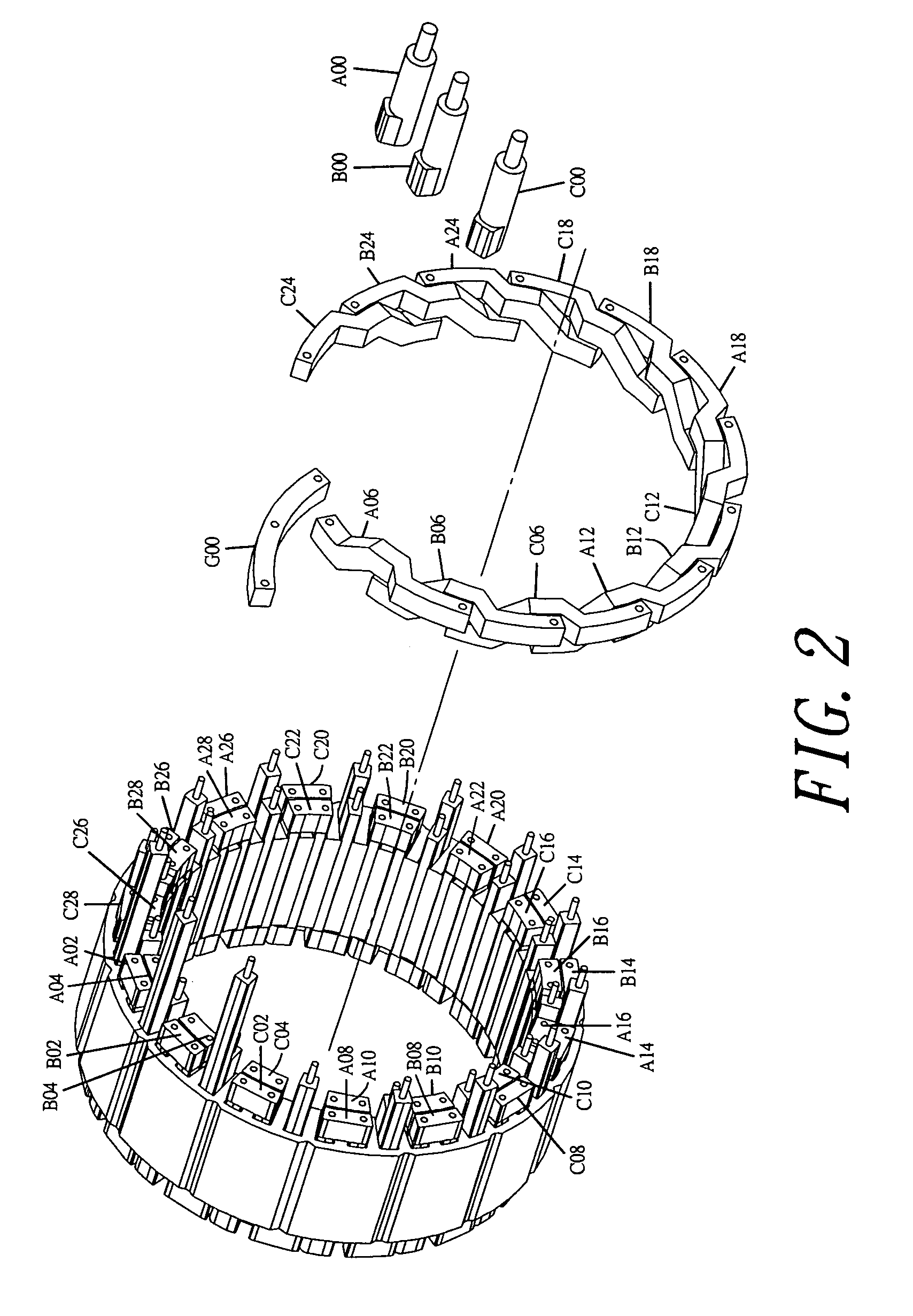
[0030]The stator winding structure in the present invention is a collective winding structure so the number of coil slots and the number of electrodes of rotors are related to a definite extent. The following lists are different combinations of the number of coil slots and electrodes of the rotors, which are applicable to a three-phase motor or generator with a collective winding structure.

[0031]

TABLE 1Number of coil slots / number of rotor electrodes = 0.75Number of rotorNumber of coil slotselectrodes346891212161520182421282432

[0032]

TABLE 2Number of coil slots / number of rotor electrodes = 1.125Number of coil slotsNumber of rotor electrodes981816272436324540

[0033]

TABLE 3Number of coil slots / number of rotor electrodes = 1.5Number of rotorNumber of coil slotselectrodes3264961281510181221142416

[0034]

TABLE 4other combinations (only listed to 33 slots)Number of rotorNumber of coil slotselectrodes12101218181421162420271827202722302030223026332233263328

[0035]A first preferred embodiment of t...


PUM

PropertyMeasurementUnit
sizesaaaaaaaaaa
sizeaaaaaaaaaa
conductingaaaaaaaaaa

Abstract

A stator winding structure of a motor or a generator includes plural separate different-shaped rod conductors combined to form a collective winding structure to take the place of a conventional winding structure which has a coil wire wound continuously. The different-shaped rod conductors can be designed in shape to match with the sizes of the coil slots to increase a slot occupied rate of the conductors and to prevent the conductors from bent during the coil winding process. The stator winding structure is especially applicable to a motor or a generator with large power and difficult in multi-electrode winding, facilitating winding and enhancing a slot occupied rate of the conductors and also reducing copper loss during output of large current.

Description

BACKGROUND OF THE INVENTION[0001]1. Field of the Invention[0002]This invention relates to a stator winding structure of a motor or a generator, particularly to one provided with separated intermediate different-shaped rod conductors combined together to form a collective winding structure to take the place of a conventional stator winding structure in which a coil wire is wound continuously. The intermediate different-shaped rod conductors in the coil slots can be designed to match with the sizes of the coil slots to increase a slot occupied rate of the conductors, able to prevent the coil wires from being bent in a winding process, applicable to a motor or a generator with large power and difficult in multi-electrode winding, and able to facilitate winding, to increase a slot occupied rate in a multi-electrode stator structure and to lower copper loss during output of large current.[0003]2. Description of the Prior Art[0004]Generally, a motor or a generator with concentrated windin...

Claims


Application Information

Patent Timeline
Patent Type & Authority Patents(United States)
IPC IPC(8): H02K3/12H02K3/28H02K3/50
CPCH02K3/12H02K3/505H02K3/28Y10T29/49009
Inventor LIAO, GORDON
Owner UNIQUE PRODS & DESIGN
Why Eureka
Try Eureka