Vehicle headlamp apparatus

Inactive Publication Date: 2005-11-01
KOITO MFG CO LTD
View PDF4 Cites 37 Cited by
  • Summary
  • Abstract
  • Description
  • Claims
  • Application Information

AI Technical Summary

Benefits of technology

[0013]Consequently, in the vehicle headlamp apparatus according to the invention, since when the terminal end of the road is determined, the location of the road which is determined to be the terminal end of the road is illuminated, the headlamp illuminates by no means a location which is too far to be determined to be the terminal end of the road from the image captured by the image capture means, and therefore, there is caused no risk that a glare is given t

Problems solved by technology

With the manual switching, however, there is case that switching is not implemented at an appropriate time, leading to another risk that people near the subject vehicle are given a glare (in the event that switching to the low beam is not implemented at a right time) or a risk that sufficient illumination is not provided ahead of the subject vehicle to thereby cause a problem of driving safety (in the event that switching to the high beam is not implemented at a right time)
However, with the aforesaid automatic headlamp light distribution switching system, although there is caused no problem while driving on a flat driving path or road, in a special driving condition, there is caused a problem that the safety of traffic is endange

Method used


Image

  • Vehicle headlamp apparatus
  • Vehicle headlamp apparatus
  • Vehicle headlamp apparatus

Examples


Embodiment Construction

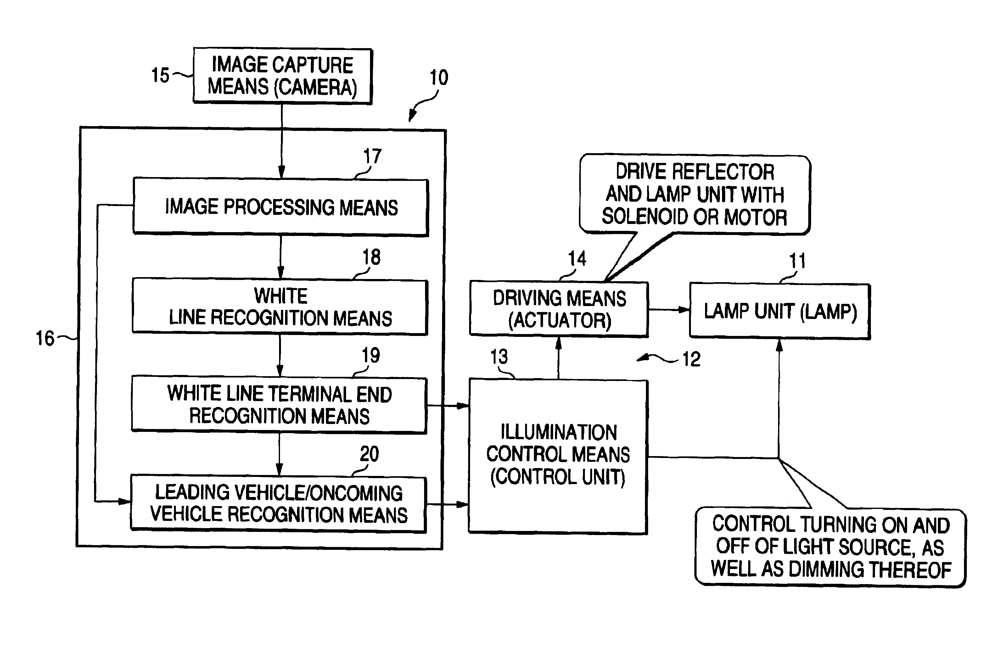
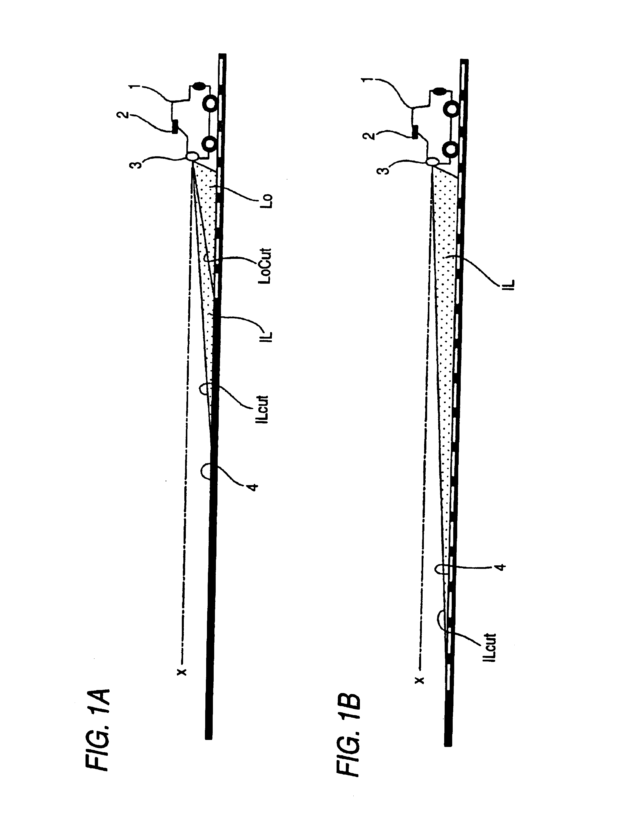
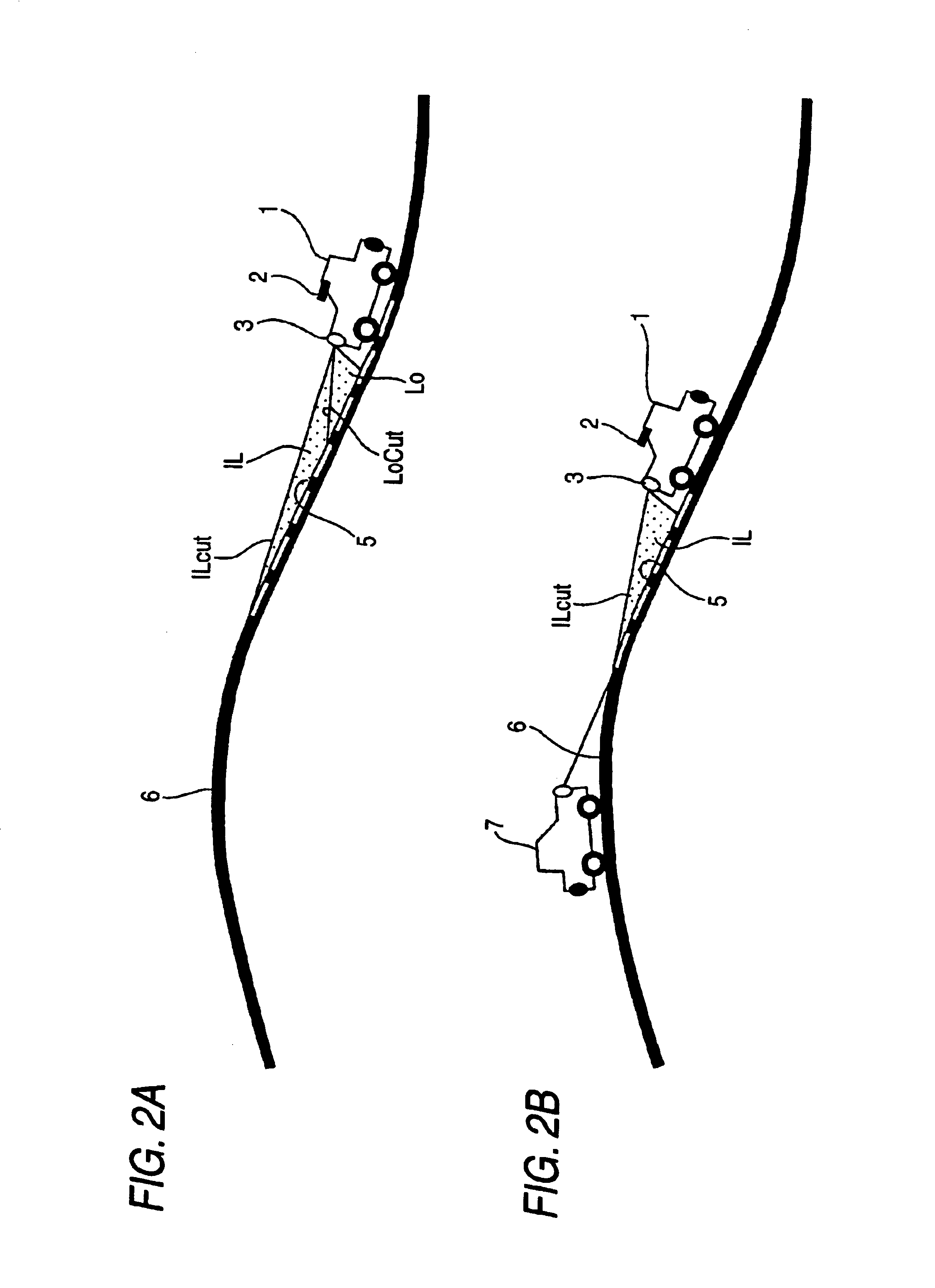
[0029]Firstly, a basic concept of the invention will be described.

[0030]When there exist leading and oncoming vehicles, it is necessary to switch to a low beam so that no glare is given to drivers of the leading and oncoming vehicles, respectively.

[0031]On the other hand, when there exist no leading and oncoming vehicles ahead, since there is little possibility that a glare is given to surroundings of the subject vehicle, it is desired to spread as long as possible the light distribution of the headlamp in a longitudinal direction (ahead of the subject vehicle) so as to brightly illuminate as far an area of the driving path as possible.

[0032]Then, when there exist no leading and oncoming vehicles, it is conceived that the low beam is automatically switched to a high beam.

[0033]In such a case, however, as has been described above, it is conceivable that a glare is given to pedestrians and bicycles which may not be able to be detected by the image capture means and further vehicles wh...


PUM


Abstract

A vehicle headlamp apparatus 10 comprising a headlamp 3 for illuminating ahead of a subject vehicle 1, an image capture means 2 for capturing an image 21 ahead of the subject vehicle, a road terminal end determining means 19 for determining a terminal end of a road ahead of the subject vehicle from the image captured by the image capture means, and a light distribution control means 12 for varying a light distribution of the head lamp so as to illuminate a location which is determined to be the terminal end of the road by the road terminal end determining means.

Description

BACKGROUND OF THE INVENTION[0001]The present invention relates to a novel vehicle headlamp apparatus. More particularly, the invention relates to a technique which ensures an optimum driving path illumination despite the existence of a leading vehicle and / or an oncoming vehicle.[0002]Conventionally, in a vehicle such as an automobile, the illumination of a driving path is implemented by headlamps thereof, and beams used for light distribution of the headlamp are roughly classified into a high beam and a low beam.[0003]The high beam is a beam for illuminating ahead mainly in a situation as found in a suburban area where there are fewer pedestrians and there exist near a subject vehicle no leading vehicle which drives ahead of the subject vehicle in the same driving direction and oncoming vehicle which drives in an opposite driving direction to that of the subject vehicle, as well as for illuminating as far as above an axis (referred to as an “optical axis at the normal time”) which p...

Claims


Application Information

Patent Timeline
IPC IPC(8): B60Q1/08B60Q1/04B60Q1/14
CPCB60Q1/085B60Q2300/054B60Q2300/056B60Q2300/122B60Q2300/322B60Q2300/41B60Q2300/42
Inventor DAICHO, YOSHINAOKAJIYAMA, SHIGETOSHI
Owner KOITO MFG CO LTD
Why Eureka
Try Eureka