
Electrical switch with placard and remote use indicator

a technology of electric switch and placard, which is applied in the direction of electrical equipment, electrical switches, tumbler/rocker switch details, etc., can solve the problems of inconvenient power cutting off of a device or group of devices, conventional wall mounted electrical switches do not typically provide a visual indication, and conventional wall mounted electrical switches do not typically provide a pla

Inactive Publication Date: 2005-11-08
PASS SEYMOUR
View PDF6 Cites 18 Cited by
  • Summary
  • Abstract
  • Description
  • Claims
  • Application Information

AI Technical Summary

Benefits of technology

"The present invention provides an electrical wiring device that includes a remote use indicator and an indicia holder to display the location of the load being powered. This device is designed for use in remote locations and can easily be identified as a visual placard. The technical effect of this invention is to provide a convenient and easy-to-use electrical device for remote locations that includes a visual identifier for easy identification."

Problems solved by technology

Conventional wall mounted electrical switches do not typically provide a visual indication that the switch is providing power to a remote location.
Further, conventional wall mounted electrical switches do not typically provide a place for a placard used in identifying the circuit controlled by the switch.
A person randomly turning switches on and off can inadvertently and inconveniently cut off power from a device or group of devices.
In addition, because wall mounted conventional electrical switches do not provide such a visual indication, lighting fixtures and other fixtures may be left on.
As a result, electrical energy may be wasted and utility bills may be higher.

Method used


Image

  • Electrical switch with placard and remote use indicator
  • Electrical switch with placard and remote use indicator

Examples


Embodiment Construction

[0014]Reference will now be made in detail to the present embodiments of the invention, examples of which are illustrated in the accompanying drawings. Whenever possible, the same reference numerals will be used throughout the drawings to refer to the same or like parts.

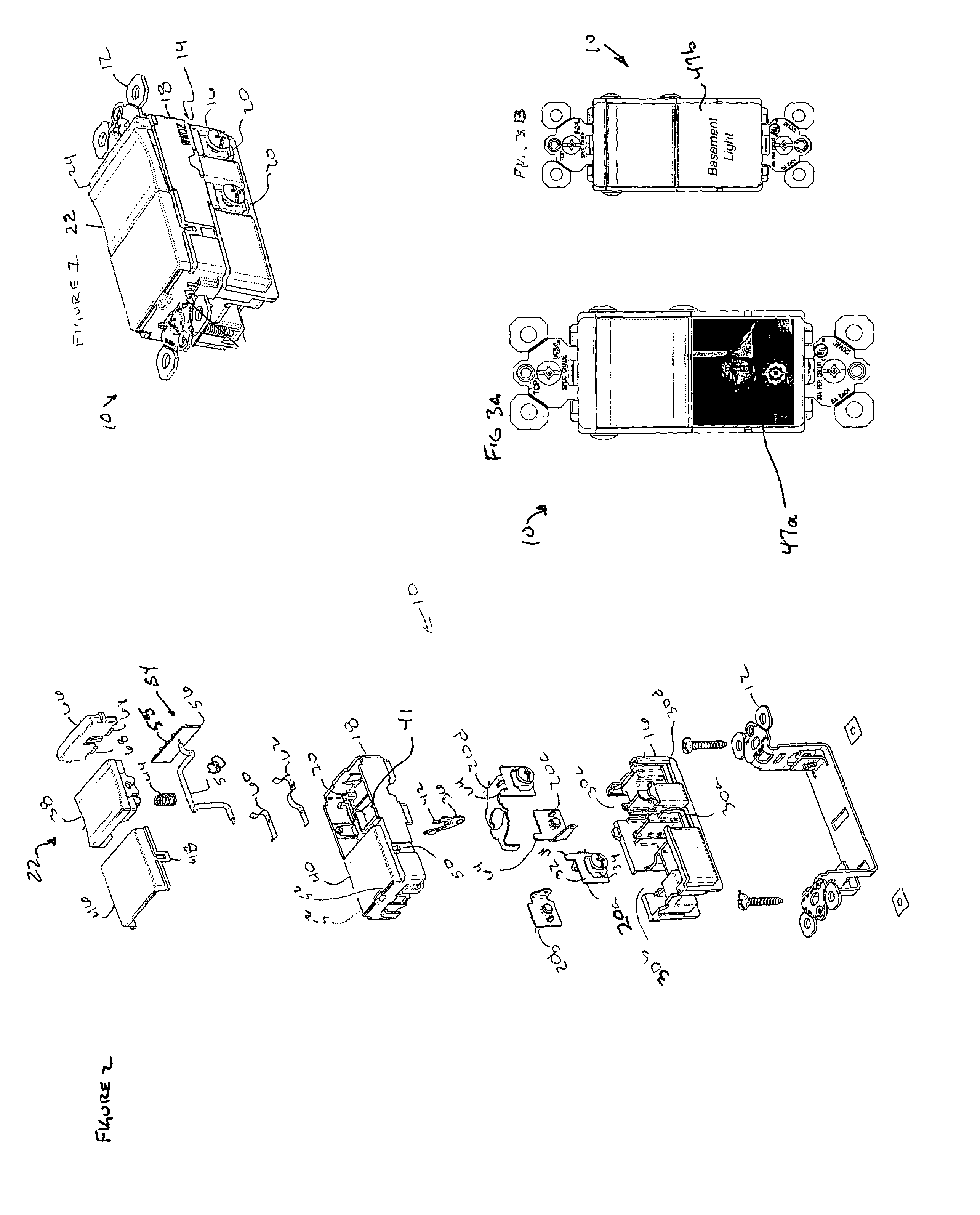
[0015]One embodiment of the electrical device of the present invention is shown in FIG. 1 and is designated generally throughout by the reference numeral 10. The electrical device 10 includes ground strap 12, a housing 14, a switch 22 disposed with the housing 14 and a remote use indicator light module 24.

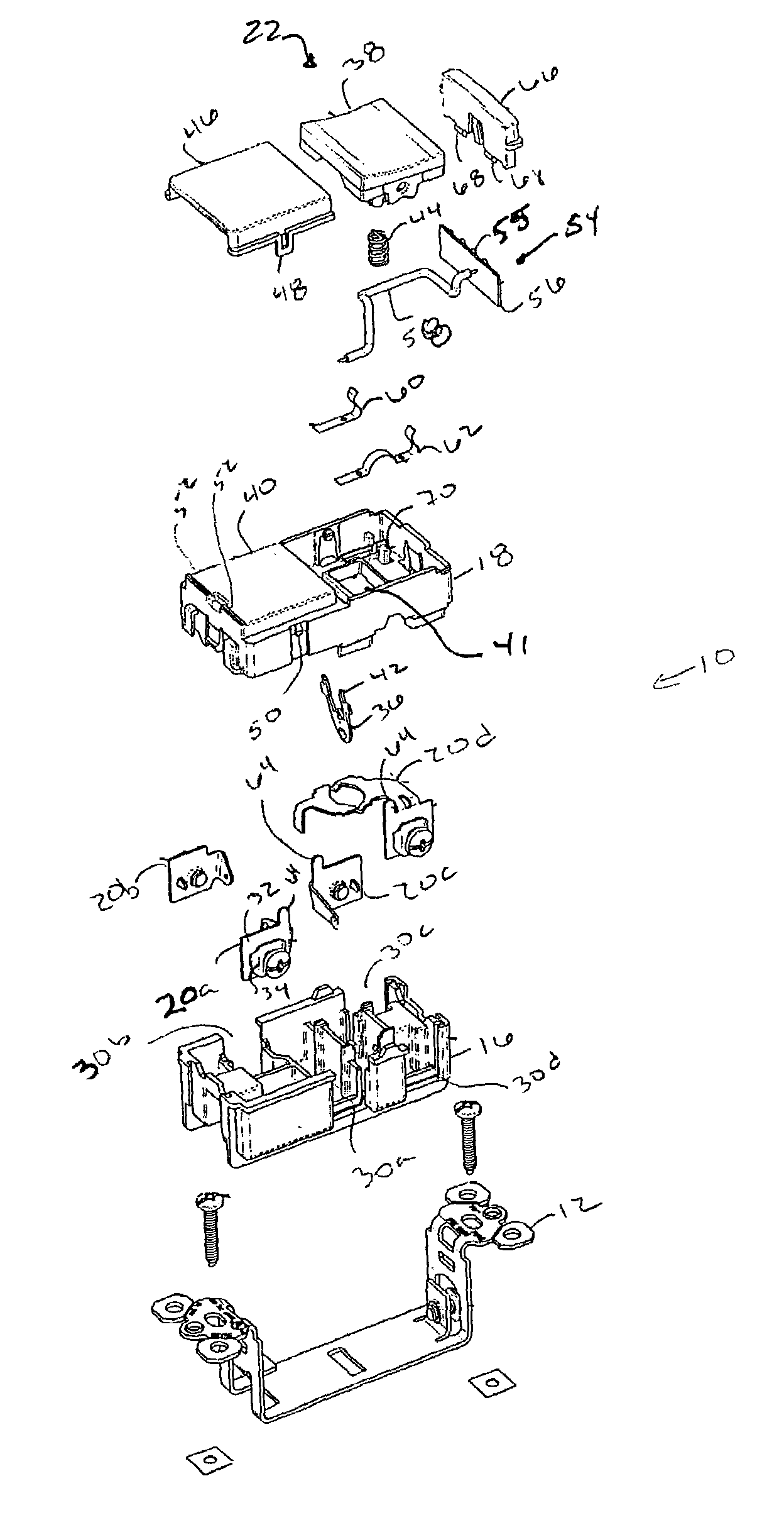
[0016]A better understanding of the embodiment of the present invention illustrated in FIG. 1 may be gained by considering FIG. 2 which is an exploded view of the electrical device 10 shown in FIG. 1. The electrical device 10 shown in FIG. 2 includes an electrical switch 22, such as, for example the three way switch, a single pole switch or a dual single pole switch unit; FIG. 2 shows a three way switch.

[0017]The el...


PUM


Abstract

An electrical device for use in an electric circuit. The electrical device includes a housing and at least one wiring device disposed within the housing. The at least one wiring device includes an electrical switch. The electrical switch includes at least one terminal member configured to be coupled to the electric circuit. The electrical switch is configured to selectively energize at least one load. The electrical device further includes a remote use indictor module disposed within the housing. The remote use indicator includes a remote use indicator circuit coupled to the electrical switch and a remote use indicator coupled to the remote use indicator circuit. The remote use indicator circuit is configured to detect when the at least one load is energized or de-energized, and actuate the remote use indicator in response thereto. The electrical device further includes an indicia holder disposed in the housing. The indicia holder is configured to display an indicia identifying a remote location of the at least one load and / or an ornamental image.

Description

CROSS REFERENCE TO RELATED APPLICATIONS[0001]This application claims the benefit of priority under 35 U.S.C. § 119(e) of Provisional U.S. patent application Ser. No. 60 / 439,370 filed on 9 Jan. 2003, the content of which is relied upon and incorporated herein by reference in its entirety.BACKGROUND OF THE INVENTION[0002]1. Field of the Invention[0003]The present invention relates to an electrical wiring device and more particularly to an electrical wiring device suitable for commercial and residential use.[0004]2. Background of the Invention[0005]Conventional wall mounted electrical switches do not typically provide a visual indication that the switch is providing power to a remote location. Further, conventional wall mounted electrical switches do not typically provide a place for a placard used in identifying the circuit controlled by the switch. As such, a person encountering the switch for the first time must use trial and error to discover the switch that applies power to the de...

Claims


Application Information

Patent Timeline
Patent Type & Authority Patents(United States)
IPC IPC(8): H01R3/00H01H9/18H01H23/02
CPCH01H9/18H01H23/025H01H2009/189H01H2219/002H01H2219/066
Inventor SAVICKI, JR., GERALD R.RADOSAVLJEVIC, DEJAN
Owner PASS SEYMOUR
Learn More