Display tray and rack assembly

a technology for display racks and racks, applied in the direction of display racks, dismountable cabinets, cabinets, etc., can solve the problem of difficult refilling of such racks

Inactive Publication Date: 2005-11-15
KIM CHANG S
View PDF11 Cites 87 Cited by
  • Summary
  • Abstract
  • Description
  • Claims
  • Application Information

AI Technical Summary

Benefits of technology

[0003]It is an object of the present invention to provide a beverage container display tray and rack that provides easy access for refilling.

Problems solved by technology

When such racks become depleted of beverage containers, they must be refilled.
Refilling such racks is difficult as it requires reaching deep inside the refrigeration unit.

Method used


Image

  • Display tray and rack assembly
  • Display tray and rack assembly
  • Display tray and rack assembly

Examples


Embodiment Construction

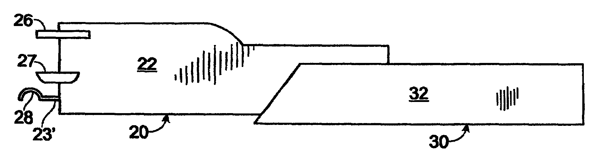
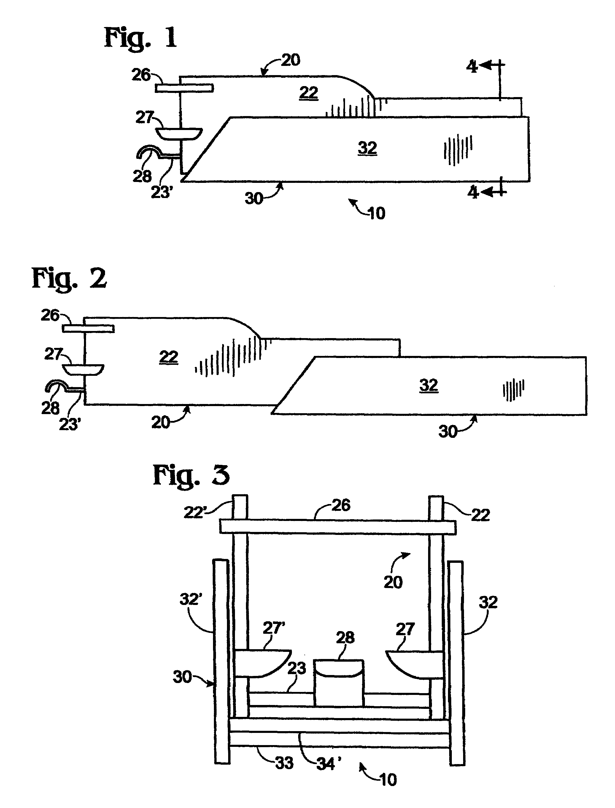
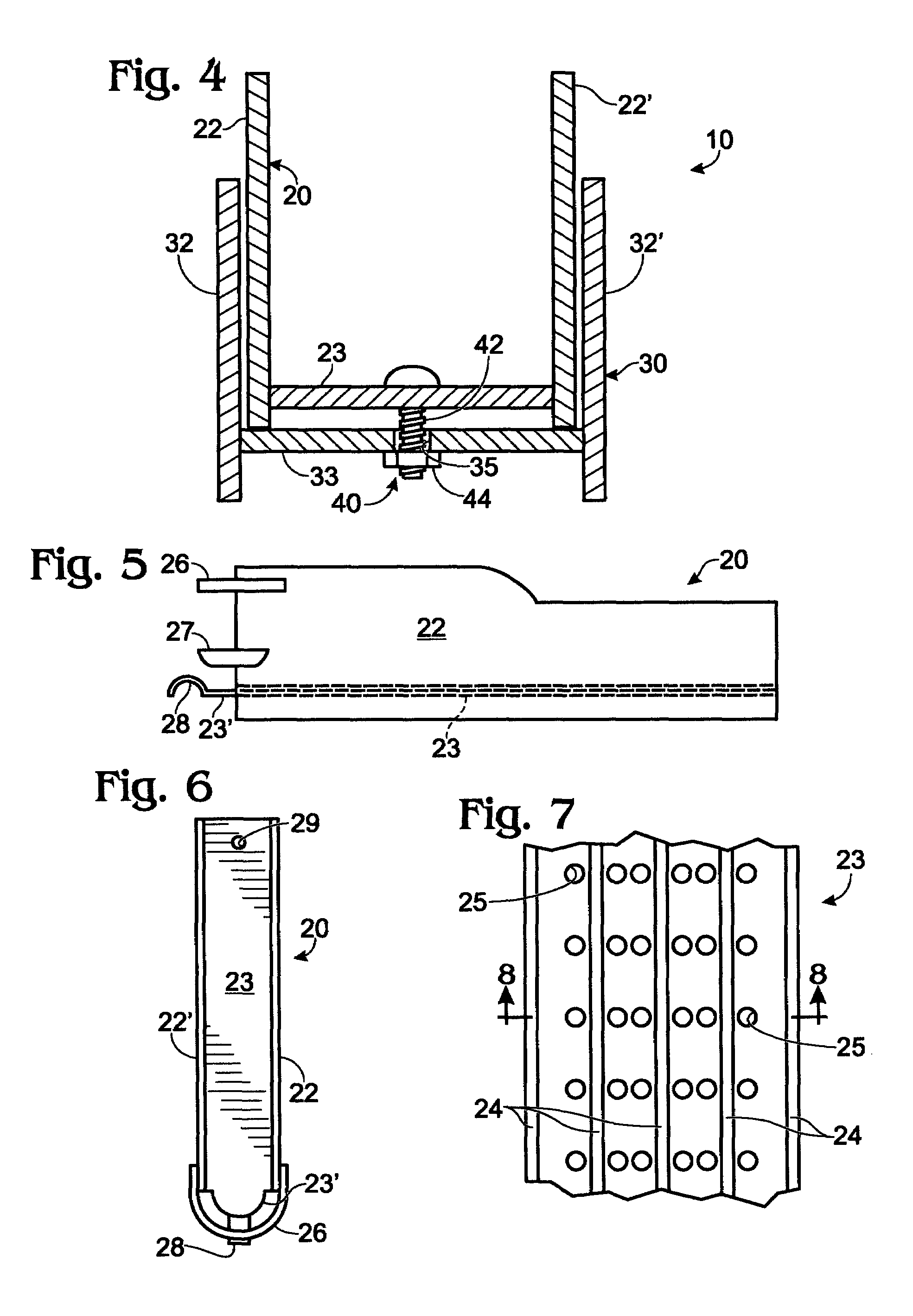
[0019]The tray and rack assembly 10 of the present invention includes a tray subassembly 20 and a rack subassembly 30.

[0020]Tray subassembly 20 includes right and left sidewalls 22 and 22′, which are identical in shape and substantially parallel to each other. The height of each of right and left sidewalls 22 and 22′ is greater in the front portion than in the rear portion, as shown. Tray subassembly 20 has no end walls.

[0021]A tray floor 23 extends between right and left sidewalls 22 and 22′ adjacent their bottom edges, but removed therefrom, as shown. That portion of the sidewalls 22, 22′ extending below tray floor 23 form a pair of legs.

[0022]Tray floor 24 has a plurality of longitudinal rails 24 extending from the upper surface thereof. Rails 24 are substantially parallel to each other and to right and left sidewalls 22 and 22′. Tray floor 24 also has a plurality of circular weep holes 25 extending therethrough. Rails 24 and weep holes 25 have not been shown in FIG. 6 for sake o...


PUM


Abstract

A tray and rack assembly for beverage containers. The assembly includes a rack subassembly and a tray subassembly slidingly engaging said rack member. The tray subassembly includes a pair of substantially parallel tray sidewalls, a tray floor extending between the lower edges of the tray sidewalls, at least one beverage container stop member extending at least partially between the outer ends of the tray sidewalls, and a tray pull member extending from the outer end of the tray. The rack subassembly includes a pair of substantially parallel rack sidewalls, and a rack floor extending between the lower edges of the rack sidewalls. Sliding attachment means are adapted to hold the tray subassembly in sliding contact with the rack subassembly and permit the tray subassembly to be extended from and inserted into the rack subassembly.

Description

BACKGROUND OF THE INVENTION[0001]The present invention relates to a display tray and rack assembly for canned or bottled beverages.[0002]Canned or bottled beverages are often placed into refrigerated display cases at their point of sale. In one type of display case the beverages are placed into display racks, each of which is designed to hold a plurality of beverage containers. Such racks are placed inside the refrigerated display case where they rest on a support shelf. The shelf and tray are inclined downwardly toward the front of the refrigeration unit. As the beverage container at the front end of the display rack is removed by a customer, the remaining containers slide downwardly by the force of gravity so that the next container in line is positioned in the front end of the display rack. Such a display rack is described in U.S. Pat. No. 5,645,176. When such racks become depleted of beverage containers, they must be refilled. Refilling such racks is difficult as it requires rea...

Claims


Application Information

Patent Timeline
Patent Type & Authority Patents(United States)
IPC IPC(8): A47B73/00A47F1/12A47F7/28
CPCA47F1/12A47F7/28
Inventor KIM, CHANG S.
Owner KIM CHANG S
Why Eureka
Try Eureka