Method of adjusting a drill bushing for a dental implant

a technology for dental implants and drill bushings, applied in the field of dental implants, can solve the problems of difficult alignment of drill bushings in the proper direction, image manipulations failing to show how the orientation of an existing drill bushing may need to be adjusted to achieve the desired drill trajectory,

Inactive Publication Date: 2005-11-22
LEO J MALIN
View PDF19 Cites 67 Cited by
  • Summary
  • Abstract
  • Description
  • Claims
  • Application Information

AI Technical Summary

Benefits of technology

[0015]Another object of some embodiments is to simultaneously adjust the trajectory i

Problems solved by technology

A drill bushing, unfortunately, can be difficult to align in the proper direction.
Although the image of implants have been tilted, translated and otherwise manipulated with respe

Method used


Image

  • Method of adjusting a drill bushing for a dental implant
  • Method of adjusting a drill bushing for a dental implant
  • Method of adjusting a drill bushing for a dental implant

Examples


Embodiment Construction

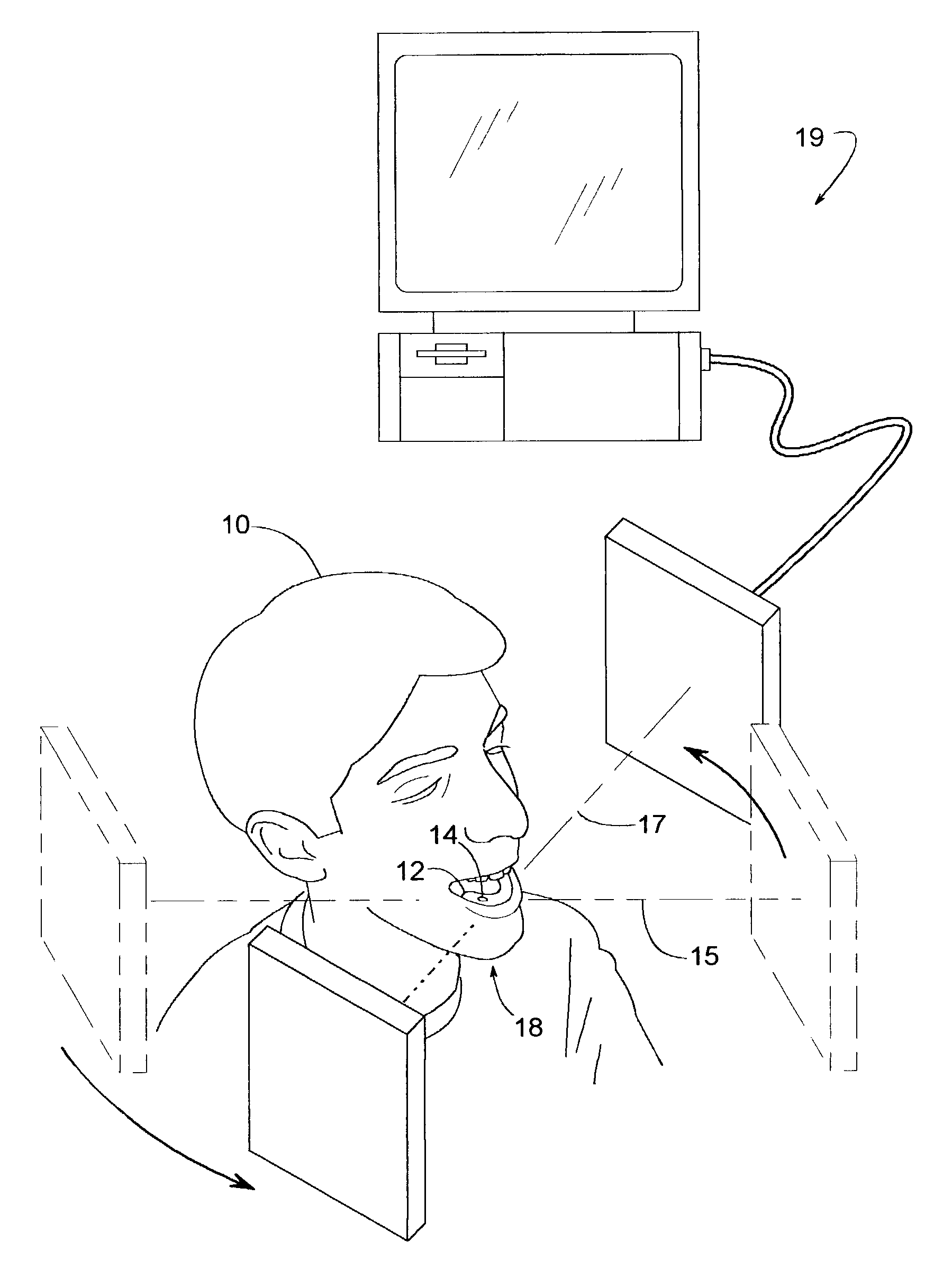
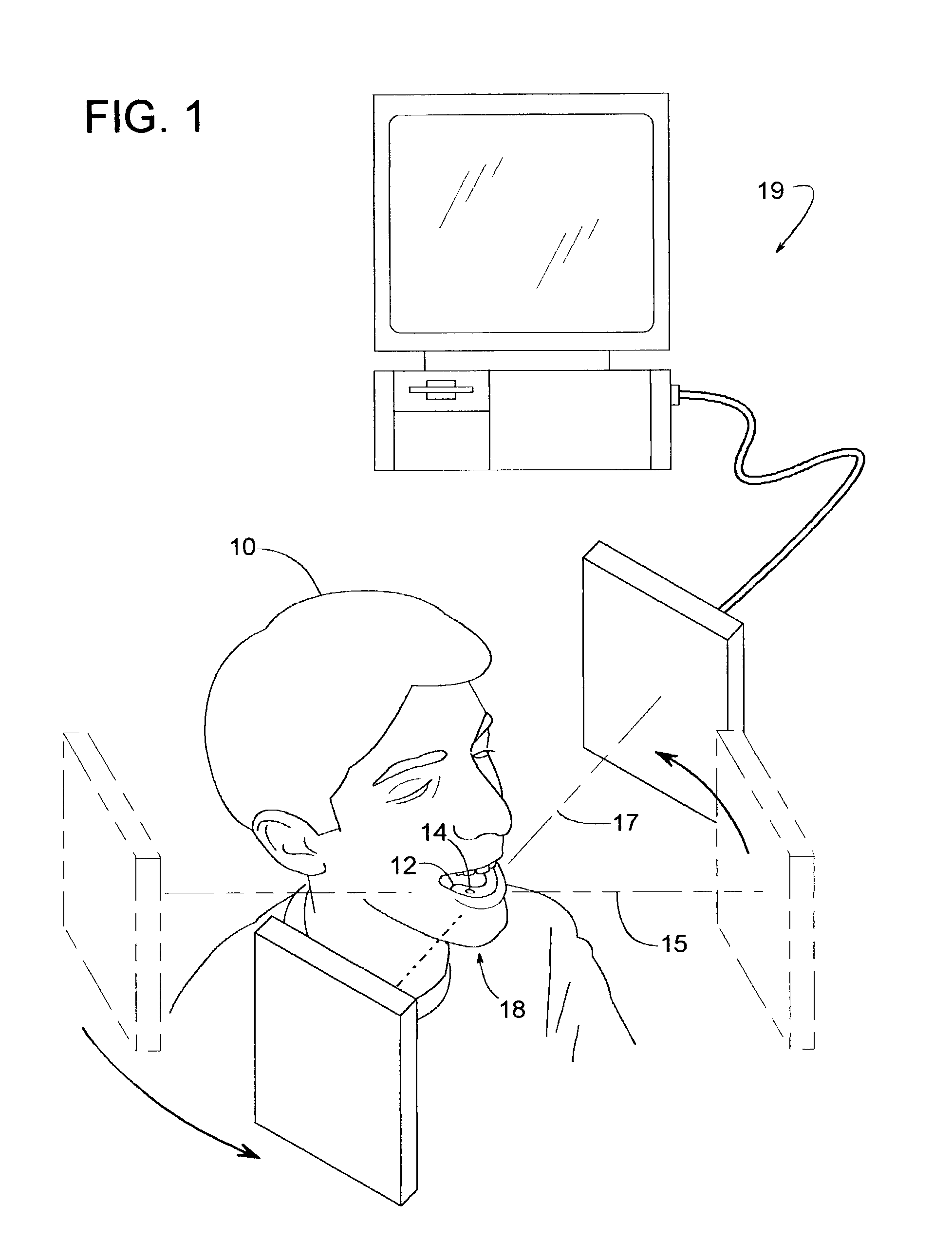
[0021]FIG. 1 shows a tomograph or a series of X-rays being taken of a patient 10 that has a surgical dental stent 12 engaging the patient's jaw. The term, “jaw” refers to that part of a patient's body that comprises one or more of the following: teeth, gums, and / or jawbone (upper or lower). Stent 12 is a conventional surgical dental stent that mates with the patient's jaw and can be produced in various ways that are well known to those skilled in the art. A drill bushing 14 is attached to stent 12 in an area of a missing tooth. Bushing 14 can help guide a drill bit in drilling a hole into the patient's jaw. An implant can then be inserted into the hole and anchored to the jaw.

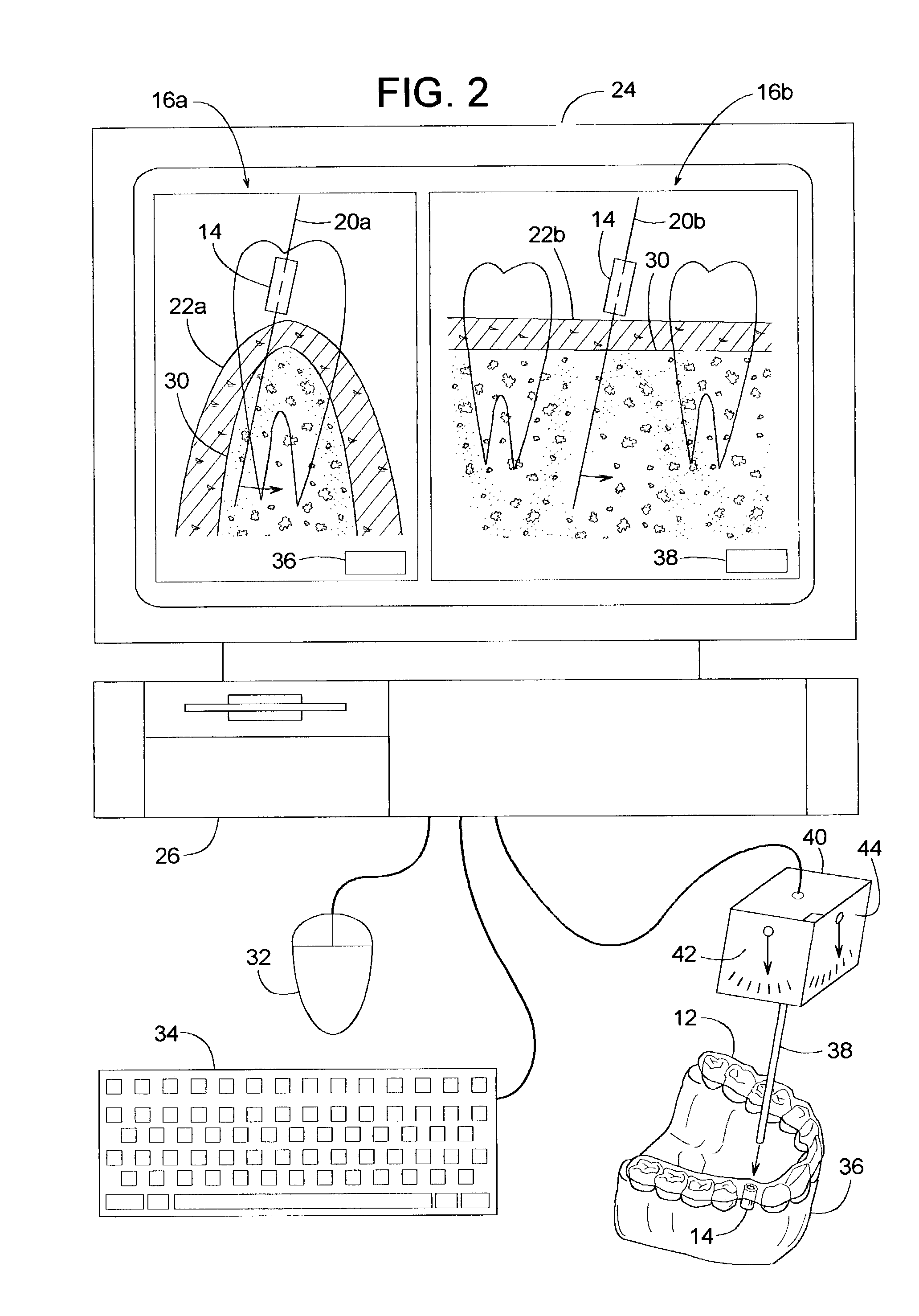
[0022]Bushing 14 is preferably made of a material that can be detected by the X-rays, so at least one overall image 16a can be created which shows bushing 14 and / or its trajectory (i.e., the bushing's longitudinal centerline) in relation to the patient's jaw 18 as shown in FIGS. 2 and 3. Overall image 16a, for ...


PUM


Abstract

A method for a dental implant process involves creating an overall image that shows a trajectory of a drill bushing in relation to a patient's jaw. The overall image shows a trajectory image that represents the trajectory of the drill bushing and a jaw image that represents the jaw. The method allows a user to move the trajectory image relative to the jaw image, which can be useful when adjusting the angular position of the actual drill bushing.

Description

BACKGROUND OF THE INVENTION[0001]1. Field of the Invention[0002]The subject invention generally pertains to dental implants and more specifically to a method for adjusting the position of a drill bushing used for installing the implant.[0003]2. Description of Related Art[0004]Various dental implant methods and devices have been developed for replacing one or more missing teeth in a person's jaw with prosthetic teeth. For many prosthetic teeth, a final product comprises three basic components: an implant, an abutment, and a crown. The crown is the exposed portion of the prosthesis that resembles one or more teeth. The implant is an anchor that becomes attached to the jawbone, and the abutment couples the crown to the implant.[0005]To install the implant, a hole is usually drilled into the patient's jawbone, and the implant is inserted into the hole.[0006]A drill bushing attached to a stent can be used to help guide the drill bit, as disclosed in PCT Publication WO 99 / 26540 and U.S. P...

Claims


Application Information

Patent Timeline
IPC IPC(8): A61C1/08A61C13/00A61C9/00
CPCA61C1/084A61C9/004A61C13/0004A61C9/0046G16H20/40
Inventor MALIN, LEO J.HARTER, ROBERT J.
Owner LEO J MALIN
Why Eureka
Try Eureka