Introducer and hemostatic valve combination and method of using the same

a technology of introduction and hemostatic valve, which is applied in the direction of catheters, guide needles, other medical devices, etc., can solve the problems of lack of adequate showing or disclosure, prior art failing to show such valve bodies directly connected to guides, etc., and achieve the effect of improving steering or transmission of torsional forces

Inactive Publication Date: 2005-11-22
THOMAS MEDICAL PRODS
View PDF4 Cites 74 Cited by
  • Summary
  • Abstract
  • Description
  • Claims
  • Application Information

AI Technical Summary

Benefits of technology

[0014]The invention overcomes these deficiencies with an introducer and hemostatic valve combination for improved steering or transmission of torsional forces that includes an introducer having a fully reinforced construction. The hemostatic valve has a body comprised of a plurality of separable portions, which form a central c

Problems solved by technology

The prior art is further deficient in that it lacks an adequate showing or disclosure relating to removable or openable hemostatic valves directly and integrally connec

Method used


Image

  • Introducer and hemostatic valve combination and method of using the same
  • Introducer and hemostatic valve combination and method of using the same
  • Introducer and hemostatic valve combination and method of using the same

Examples


embodiment 95

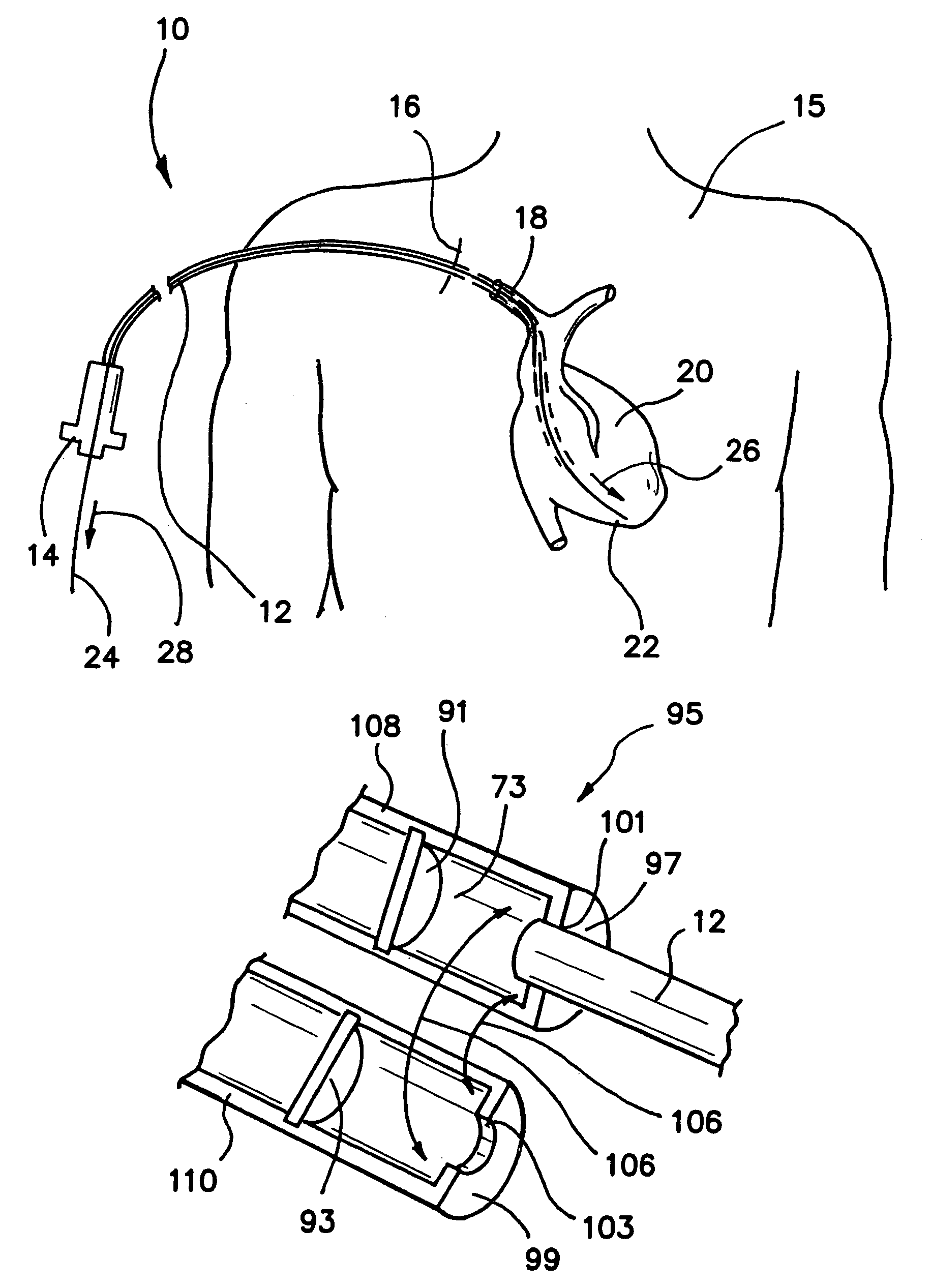
[0059]FIG. 10 shows an alternative embodiment 95 having a first valve portion 108 and a second valve portion 110. In this embodiment, introducer 12 is permanently attached to first portion 108 by insert molding or adhesion to a first aperture sector 101 in a first end wall 97. On the other hand, introducer 12 is removably and sealingly coupled to second portion 110 at a second aperture sector 103 in a second end wall 99 when the first and second portions 108, 110 are assembled together. A release agent can be applied to introducer 12 and / or sector 103 during manufacture so that when introducer 12 is insert molded to portions 108 and 110, no bond or a weakened bond is formed between introducer 12 and portion 110. Arrows 106 indicate directions of opening and closing the first and second portions 108, 110 relative to each other.

[0060]A preferred embodiment is comprised of a valve housing 38, 40, in the example of FIG. 9, connected to the guide 12 with a fluid tight connection that per...

embodiment 155

[0065]FIGS. 12 and 13 show a further additional alternative embodiment 155 of the hemostatic valve that includes a first portion 158 and a second portion 160. A first finger grip 163 is integrally connected to the first portion 158. A second finger grip 165 is integrally connected to the second portion 160. A biasing means in the form of a spring 167 urges the finger grips 163, 165 apart. Spring 167 also urges the first and second portions 158, 160 together by virtue of the crossed configuration of the finger grips 163, 165. This embodiment includes a tongue 169 and groove 170 for locking the first and second portions 158, 160 in a closed, sealed condition integral with the introducer 12 relative to the ambient when in use. Here again a tab 149 permanently affixed to introducer 12 is provided.

[0066]FIG. 13 is a modified sectional view taken along lines XIII—XIII of FIG. 12. FIG. 13 shows the hemostatic valve 155 in an opening configuration. Like the various embodiments described abo...


PUM


Abstract

An introducer and hemostatic valve for improved torsional guidance and kink resistance includes an entirely circumferentially reinforced introducer connected directly to a valve body formed of a plurality of separable portions and housing a valve element in a central chamber thereof. The plurality of portions may be attached to the introducer during formation of the introducer, the valve body, or both. Alternatively, the plurality of portions may be attached to the introducer by assembly of the portions together in a surrounding relation to the introducer. In use, the plurality of portions are separated from each other and the introducer is cut along its length in order to withdraw the introducer and hemostatic valve over an enlarged proximal end of an access device as the introducer is pulled from the patient's body.

Description

BACKGROUND OF THE INVENTION[0001]1. Field of the Invention[0002]The invention relates generally to introducers, sheaths, guides or catheters and hemostatic valves, and more specifically to a nonfrangible guide or introducer and hemostatic valve combination and the method of using the same.[0003]2. Description of the Prior Art[0004]For purposes of this specification a sheath is defined as an un-reinforced hollow tube, which may contain lines of weakness to aid in the peeling apart of the sheath.[0005]A guide is a braid-reinforced hollow tube that cannot be peeled, or torn away simply by pulling on it, but must be sliced or cut open with a cutter, slicer, slitter or other tool. Further, while the guide is disclosed as braided, any construction of the guide, which allows the guide to be torsionally stiff enough such that a rotation of its proximal end is transmitted in its substantial entirety to its distal end when the guide is in use, is considered equivalent. Thus, the guide is term...

Claims


Application Information

Patent Timeline
IPC IPC(8): A61M39/06A61M39/02A61M25/06A61M39/00A61M25/08
CPCA61M39/06A61M25/0662A61M39/0606A61M2039/062
Inventor KURTHARMOUR, ANDREW WILLIAMNEILANS, SARAH AMBRYN
Owner THOMAS MEDICAL PRODS
Why Eureka
Try Eureka